Troubleshooting
GP Repair
wc_tx000548gb.fm
106
6.26 Checking Anit-Afterfire Solenoid (AAS) Circuit
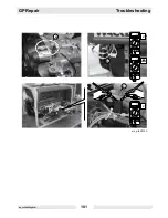
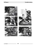
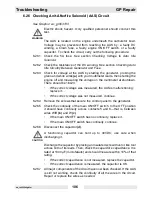
See Graphic: wc_gr003133
Electric shock hazard. Only qualified personnel should conduct this
test.
The AAS is located on the engine underneath the carburetor bowl.
Voltage may be prevented from reaching the AAS by: a faulty DC
winding, a blown fuse, a faulty engine ON/OFF switch, or a faulty
capacitor. To check the circuit, carry out the following procedure:
6.26.1 Check the 5A fuse. See section
Checking Voltage to Auto Idle
Solenoid.
6.26.2 Check the resistance of the DC winding. See section
Checking Auto
Idle Circuitry Between Generator and Fuse.
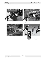
6.26.3 Check for voltage at the AAS by starting the generator, probing the
green and white wires
(a)
with your multimeter leads, then shutting the
engine off and measuring the voltage on the multimeter at shutdown.
There should be 18±2V.
•
If the correct voltage was measured, the AAS is malfunctioning;
replace it.
•
If the correct voltage was not measured, continue.
6.26.4 Remove the screws that secure the control panel to the generator.
6.26.5 Check the continuity of the main ON/OFF switch. In the OFF position
it should have continuity across contacts 5 and 6—that is, between
wires W/R
(b)
and W
(c)
.
•
If the main ON/OFF switch has no continuity, replace it.
•
If the main ON/OFF switch has continuity, continue.
6.26.6 Disconnect the capacitor
(d)
.
A functioning capacitor can hold up to 30VDC; use care when
discharging it.
Discharge the capacitor by placing an insulated screw driver or like tool
across both of its leads. Then, check the capacitor’s capacitance. It is
rated at 1000 µF (microfarads) and should measure within 10% of that
rating.
•
If the correct capacitance is not measured, replace the capacitor.
•
If the correct capacitance is measured, the capacitor is OK.
6.26.7 All major components of the circuit have now been checked. If the AAS
is still not working, check the continuity of all the wires in the circuit.
Repair or replace the wires as needed.
WARNING
CAUTION
Summary of Contents for GP 3800A
Page 2: ......
Page 13: ...GP Repair Safety Information wc_si000169gb fm 9 1 4 Label Locations GND 88897...
Page 25: ...GP Repair Technical Data wc_td000169gb fm 21 Notes...
Page 50: ...Maintenance GP Repair wc_tx000546gb fm 46 4 11 Electrical Schematic GP 2500A...
Page 52: ...Maintenance GP Repair wc_tx000546gb fm 48 4 13 Electrical Schematic GP 3800A 0620010 rev 104...
Page 54: ...Maintenance GP Repair wc_tx000546gb fm 50 4 15 Electrical Schematic GP 3800A 0620010 rev 103...
Page 60: ...Maintenance GP Repair wc_tx000546gb fm 56 4 21 Electrical Schematic GP GPS 5600A 6600A rev 104...
Page 62: ...Maintenance GP Repair wc_tx000546gb fm 58 4 23 Electrical Schematic GP GPS 5600A 6600A rev 103...
Page 68: ...Maintenance GP Repair wc_tx000546gb fm 64 4 29 Engine Schematic all GP GPS 3800A 5600A 6600A...
Page 70: ...Maintenance GP Repair wc_tx000546gb fm 66 Notes...
Page 77: ...GP Repair Troubleshooting wc_tx000548gb fm 73 wc_gr003415 z y...
Page 87: ...GP Repair Troubleshooting wc_tx000548gb fm 83 Notes...
Page 95: ...GP Repair Troubleshooting wc_tx000548gb fm 91 wc_gr003148 b c d a...
Page 112: ...Troubleshooting GP Repair wc_tx000548gb fm 108 Notes...
Page 115: ...GP Repair Disassembly Assembly Procedures wc_tx000549gb fm 111 wc_gr003136 c e f f h f g a b d...
Page 119: ...GP Repair Disassembly Assembly Procedures wc_tx000549gb fm 115 wc_gr003138 a d e c b f g i h...
Page 121: ...GP Repair Disassembly Assembly Procedures wc_tx000549gb fm 117 wc_gr003139 d d c c e f a b...
Page 123: ...GP Repair Disassembly Assembly Procedures wc_tx000549gb fm 119 wc_gr003141 c a b d e f...
Page 124: ...Disassembly Assembly Procedures GP Repair wc_tx000549gb fm 120...
Page 129: ......

