Theory of Operation
GP Repair
wc_tx000547gb.fm
68
5.2
Windings and Fields
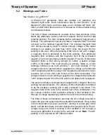
See Graphic: wc_gr003117
In Wacker GP generators there are multiple coil (winding) and
magnetic field pairs. Each combination has its own function. In all
Model GP 2500 there are three pairs and in Models GP 3800, GP
5600, and GP 6600 there are four. A discussion of these field/winding
combinations follows.
The first of these combinations consists of the main windings in the
stator
(a)
(stationary portion) and the magnetic field of the rotor
(b)
(rotating portion). The rotor contains both a permanent magnet and a
winding. The permanent magnet provides a magnetic field. This field
is known as the residual magnetic field. The residual magnetic field
isn’t strong enough by itself to induce enough voltage in the stator
winding to be usable (it’s less than 120V); thus, the reason for the
winding in the rotor. When the winding of the rotor is fed a DC voltage,
a magnetic field is produced in the rotor winding. This additional
magnetic field combines with the magnetic field of the permanent
magnet. (The rotor becomes an electromagnet.) The sum of these two
magnetic fields is then strong enough to induce a usable voltage
(120V) in the stator. The main winding is actually made up of two
windings referred to as main winding 1, and main winding 2. The
voltage induced in main winding 1 supplies the voltage to the left-side
120V receptacle and the 3-prong 120V receptacle underneath it. It also
provides 120 of the 240 volts found at the 240V receptacle. The
voltage induced in main winding 2 supplies the voltage to the right-side
120V receptacle and 120 of the 240 volts found at the 240V receptacle.
The second of these combinations provides the DC voltage to the rotor
winding mentioned earlier. The winding of this combination is referred
to as the excitation winding and is also contained in the stator. The
magnetic field of the rotor is the second half of the combination. The
AC voltage induced in the excitation winding is first rectified to DC
through a voltage regulator
(c)
before it is sent to the rotor winding.
The third of these combinations provides the DC voltage required to
power the auto idle system and the anti-afterfire solenoid. The winding
of this combination is known as the DC winding. It is also part of the
stator, and like the others, the rotor supplies the magnetic field.
The AC
voltage induced in the DC winding is first rectified to DC through a
diode pack
(d)
before it is sent to the auto idle circuit.
Note:
The DC
winding is not included on GP 2500A models.
Summary of Contents for GP 3800A
Page 2: ......
Page 13: ...GP Repair Safety Information wc_si000169gb fm 9 1 4 Label Locations GND 88897...
Page 25: ...GP Repair Technical Data wc_td000169gb fm 21 Notes...
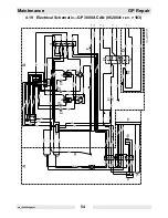
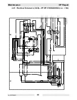
Page 50: ...Maintenance GP Repair wc_tx000546gb fm 46 4 11 Electrical Schematic GP 2500A...
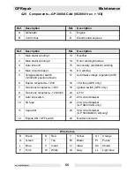
Page 52: ...Maintenance GP Repair wc_tx000546gb fm 48 4 13 Electrical Schematic GP 3800A 0620010 rev 104...
Page 54: ...Maintenance GP Repair wc_tx000546gb fm 50 4 15 Electrical Schematic GP 3800A 0620010 rev 103...
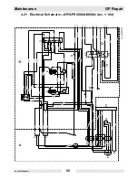
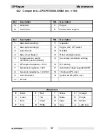
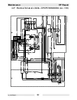
Page 60: ...Maintenance GP Repair wc_tx000546gb fm 56 4 21 Electrical Schematic GP GPS 5600A 6600A rev 104...
Page 62: ...Maintenance GP Repair wc_tx000546gb fm 58 4 23 Electrical Schematic GP GPS 5600A 6600A rev 103...
Page 68: ...Maintenance GP Repair wc_tx000546gb fm 64 4 29 Engine Schematic all GP GPS 3800A 5600A 6600A...
Page 70: ...Maintenance GP Repair wc_tx000546gb fm 66 Notes...
Page 77: ...GP Repair Troubleshooting wc_tx000548gb fm 73 wc_gr003415 z y...
Page 87: ...GP Repair Troubleshooting wc_tx000548gb fm 83 Notes...
Page 95: ...GP Repair Troubleshooting wc_tx000548gb fm 91 wc_gr003148 b c d a...
Page 112: ...Troubleshooting GP Repair wc_tx000548gb fm 108 Notes...
Page 115: ...GP Repair Disassembly Assembly Procedures wc_tx000549gb fm 111 wc_gr003136 c e f f h f g a b d...
Page 119: ...GP Repair Disassembly Assembly Procedures wc_tx000549gb fm 115 wc_gr003138 a d e c b f g i h...
Page 121: ...GP Repair Disassembly Assembly Procedures wc_tx000549gb fm 117 wc_gr003139 d d c c e f a b...
Page 123: ...GP Repair Disassembly Assembly Procedures wc_tx000549gb fm 119 wc_gr003141 c a b d e f...
Page 124: ...Disassembly Assembly Procedures GP Repair wc_tx000549gb fm 120...
Page 129: ......

