background image

Maintenance

GP Repair

wc_tx000546gb.fm

52

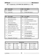
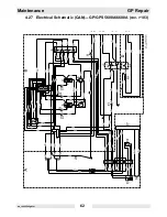
4.17 Electrical Schematic—GP 3800A CAN (0620041 rev. < 104)

Summary of Contents for GP 3800A

Page 1: ...www wackergroup com Generator GP 2500A GP 3800A GP 5600A GPS 5600A GP 6600A GPS 6600A REPAIR MANUAL 0160415en 001 0806 0 1 6 0 4 1 5 E N...

Page 2: ......

Page 3: ...by misuse or neglect of the unit should be brought to the attention of the operator to prevent similar occurrences from happening in the future This manual provides information and procedures to safe...

Page 4: ...qualified and rated by the United States Forest Service for this purpose In order to comply with local laws regarding spark arresters consult the engine distributor or the local Health and Safety Admi...

Page 5: ...CAN 18 2 6 Engine GP GPS 5600A 5600A CAN 20 2 7 Generator GP GPS 6600A 6600A CAN 22 2 8 Engine GP GPS 6600A 6600A CAN 24 3 Operation 25 3 1 Information Regarding Operation 25 3 2 Determining Power Req...

Page 6: ...52 4 18 Components GP 3800A CAN 0620041 rev 104 53 4 19 Electrical Schematic GP 3800A CAN 0620041 rev 103 54 4 20 Components GP 3800A CAN 0620041 rev 103 55 4 21 Electrical Schematic GP GPS 5600A 6600...

Page 7: ...ing 88 6 16 Checking AVR s Sensing Wires GP 2500A 90 6 17 Checking AVR s Sensing Wires 92 6 18 Confirming a Malfunctioning AVR 94 6 19 Checking and Installing the Voltage Selector Switch VSS 96 6 20 H...

Page 8: ...symbol to avoid possible injury or death DANGER indicates a hazardous situation which if not avoided will result in death or serious injury WARNING indicates a hazardous situation which if not avoide...

Page 9: ...ed in both this manual and the engine manual and familiarize yourself with the location and proper use of all controls Inexperienced operators should receive instruction from someone familiar with the...

Page 10: ...at least one meter three feet away from structures buildings and other equipment during use 1 1 16 ALWAYS keep the area immediately surrounding and underneath the machine clean neat and free of debris...

Page 11: ...osure to carbon monoxide can cause loss of consciousness and may lead to death 1 2 2 DO NOT smoke while operating the machine 1 2 3 DO NOT smoke when refueling the engine 1 2 4 DO NOT refuel a hot or...

Page 12: ...move the machine and allow the machine to dry before servicing 1 3 5 DO NOT service the machine if your clothing or skin is wet 1 3 6 DO NOT allow untrained personnel to service this equipment Only tr...

Page 13: ...GP Repair Safety Information wc_si000169gb fm 9 1 4 Label Locations GND 88897...

Page 14: ...nal pictorial labels where needed These labels are described below Label Meaning WARNING Hot surface CAUTION Read and understand the supplied Operator s Manuals before operating this machine Fail ure...

Page 15: ...fm 11 Close main circuit breaker Check the fuel level Open the fuel flow valve Press engine switch to ON position GPS Press ignition switch GP Pull the rewind starter Open main circuit breaker Press e...

Page 16: ...into utility lines This may result in electrocution of utility workers fire or explo sion Connections to a building s electrical sys tem must be made by a qualified electrician and comply with all app...

Page 17: ...Repair Safety Information wc_si000169gb fm 13 This machine may be covered by one or more patents DANGER No sparks flames or burning objects near machine Shut off the engine before refueling Label Mean...

Page 18: ...put W 2500 Continuous Output W 2250 Type Single voltage single phase Auto voltage regulator system AC Voltages Available volts phase 120 1 Frequency Hz 60 Power Factor 1 0 AC receptacles 125V GFI dupl...

Page 19: ...BPR6ES W20EPR U Electrode Gap mm in 0 7 0 8 0 028 0 031 Operating Speed Max rpm 3600 Air Cleaner type Dry type with oil wetted foam pre cleaner Engine Lubrication oil grade SAE 10W30 service class SF...

Page 20: ...W 3400 Type Dual voltage single phase Auto voltage regulator system AC Voltages Available volts phase 120 240 1 Frequency Hz 60 Power Factor 1 0 AC receptacles 125V GFI duplex 125V GFI duplex 125V twi...

Page 21: ...Model GX 240 Rated Power kW Hp 6 8 Spark Plug BPR6ES W20EPR U Electrode Gap mm in 0 7 0 8 0 028 0 031 Operating Speed max rpm 3600 Air Cleaner type Dry type with oil wetted foam pre cleaner Engine Lu...

Page 22: ...phase Auto voltage regulator system AC Voltages Available volts phase 120 240 1 Frequency Hz 60 Power Factor 1 0 AC receptacles 125V GFI duplex 125V GFI duplex 125V twist lock 125V 250V twist lock amp...

Page 23: ...ltage regulator system AC Voltages Available volts phase 120 240 1 Frequency Hz 60 Power Factor 1 0 AC receptacles 125V GFI duplex 125V GFI duplex 125V twist lock 125V 250V twist lock amp amp amp amp...

Page 24: ...1 Rated Power kW Hp 8 2 11 Spark Plug BPR6ES W20EPR U Electrode Gap mm in 0 7 0 8 0 028 0 031 Operating Speed Max rpm 3600 Air Cleaner type Dry type with oil wetted foam pre cleaner Battery type ratin...

Page 25: ...GP Repair Technical Data wc_td000169gb fm 21 Notes...

Page 26: ...ase Auto voltage regulator system AC Voltages available volts phase 120 240 1 Frequency Hz 60 Power Factor 1 0 AC receptacles 125V GFI duplex 125V GFI duplex 125V twist lock 125V 250V twist lock amp a...

Page 27: ...age regulator system AC Voltages available volts phase 120 240 1 Frequency Hz 60 Power Factor 1 0 AC receptacles 125V GFI duplex 125V GFI duplex 125V twist lock 125V 250V twist lock amp amp amp amp 20...

Page 28: ...Rated Power kW Hp 9 7 13 Spark Plug Champion RN10Y Electrode Gap mm in 0 7 0 8 0 028 0 031 Operating Speed Max rpm 3600 Air Cleaner type Dry type with oil wetted foam pre cleaner Battery type rating...

Page 29: ...information in Approximate Starting Power Requirements is offered only as a general guideline to help you in determining power requirements for different types of equipment Check with your nearest Wac...

Page 30: ...0545gb fm 26 If the wattage is not given for a particular tool or appliance it can be calculated by multiplying its voltage and amperage requirements Single Phase VOLTS x AMPS WATTS Three Phase VOLTS...

Page 31: ...ust fumes make sure the exhaust piping is large enough to prevent excessive back pressure to the engine Back pressure reduces engine efficiency and may cause the engine to overheat Exhaust gas from th...

Page 32: ...de also affects the cooling capacity of air the higher the altitude the less dense the air is and thus the lower its ability to transfer heat For every increase in altitude of 500 m 1650 ft above 1000...

Page 33: ...r000544 A ground connection a is located on the generator frame For proper operating safety this ground terminal must be connected to a good ground source This ground connection must comply with Natio...

Page 34: ...pair wc_tx000545gb fm 30 3 8 Control Panel See Graphic wc_gr002324 Ref Description Ref Description a GFI duplex receptacle 120V d GFI test button b Circuit breaker 20 Amp e GFI reset button c Duplex r...

Page 35: ...ption Ref Description a Engine switch g GFI test button b Auto idle switch h GFI reset button c Twist lock receptacle 120V j Twist lock receptacle 120 240V d Main circuit breaker m 20A circuit breaker...

Page 36: ...ef Description a Engine Switch g GFI test button b Auto Idle Switch h GFI reset button c Twist lock receptacle 120V j Twist lock receptacle 120 240V d Main Circuit Breaker k Ignition Switch GPS only e...

Page 37: ...eceptacle in The RESET button g will pop out The power is now off at the receptacles If the RESET button does not pop out the GFI is not working Do not run the generator until the problem can be corre...

Page 38: ...dle switch to AUTO The AUTO setting is recommended while the generator is running to minimize fuel consumption To avoid extended engine warm up periods keep switch set to OFF when starting the engine...

Page 39: ...between the three receptacles In dual voltage mode both the 120V and 120 240V receptacles are powered lower watts are available on receptacles f1 f2 c The 120 240V twist lock receptacle j should be u...

Page 40: ...e engine switch to ON b1 and pull the starter rope f 3 16 5 On electric start engines press the ignition switch k and hold until the engine starts Release the switch after the engine starts CAUTION DO...

Page 41: ...ff and disconnect all tools and appliances attached to the generator 3 17 2 Place the main circuit breaker in the OFF position a2 3 17 3 Turn the engine switch to OFF b2 3 17 4 Close the fuel valve d2...

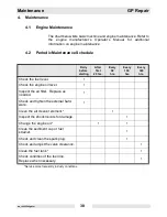
Page 42: ...r first 20 hrs Every 50 hrs Every 100 hrs Every 300 hrs Check the fuel level Check the engine oil level Inspect the air filter Replace as needed Check and tighten the external hard ware Clean the air...

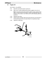
Page 43: ...e interests of environmental protection place a plastic sheet and a container under the machine to collect any liquid that drains off Dispose of this liquid in accordance with environmental protection...

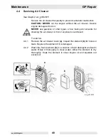
Page 44: ...r other types of low flash point solvents for cleaning the air cleaner A fire or explosion could result To service 4 4 1 Remove the air cleaner cover a Inspect the element b for holes or tears Replace...

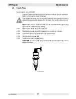
Page 45: ...ng the engine Do not touch the muffler while it is hot Note Refer to the Technical Data for the recommended spark plug type and the electrode gap setting 4 5 1 Remove the spark plug and inspect it 4 5...

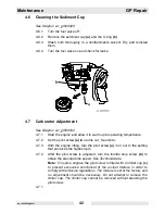
Page 46: ...et the pilot screw a two turns out See Note 4 7 3 With the engine idling turn the pilot screw a in or out to the setting that produces the highest rpm 4 7 4 After the pilot screw is adjusted turn the...

Page 47: ...ntrolled by a governor which automatically adjusts to varying loads on the engine to maintain a constant speed There is no throttle control To set the engine to the proper speed Turn the speed adjusti...

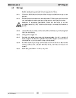
Page 48: ...ventilated area DO NOT drain the fuel tank in an area with flames or sparks 4 9 3 Loosen the drain screw on the carburetor and drain any remaining fuel from the carburetor 4 9 4 Change the engine oil...

Page 49: ...he engine fuel valve to the OFF position 4 10 2 Position the generator level to prevent fuel from spilling 4 10 3 Secure the generator by tying it down with a suitable rope When transporting the machi...

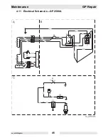
Page 50: ...Maintenance GP Repair wc_tx000546gb fm 46 4 11 Electrical Schematic GP 2500A...

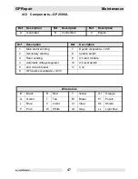
Page 51: ...n 1 Main stator winding 7 Duplex receptacle 120V 2 Secondary winding 8 Ignition switch 3 Rotor winding 9 Oil alert module 4 Automatic voltage regulator 10 Oil level switch 5 20A circuit breaker 11 Coi...

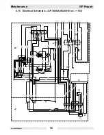
Page 52: ...Maintenance GP Repair wc_tx000546gb fm 48 4 13 Electrical Schematic GP 3800A 0620010 rev 104...

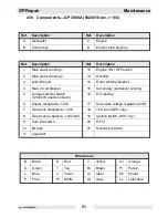
Page 53: ...3 Rectifier 4 Main circuit breaker 14 Rotor winding brushes 5 Voltage selector switch 120 240V position shown 15 Secondary excitation winding 6 GFI duplex receptacle 120V 16 DC winding 7 Twist lock re...

Page 54: ...Maintenance GP Repair wc_tx000546gb fm 50 4 15 Electrical Schematic GP 3800A 0620010 rev 103...

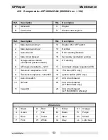
Page 55: ...ng brushes 4 Main circuit breaker 15 Secondary excitation winding 5 Voltage selector switch 120 240V position shown 16 DC winding 6 Duplex receptacle 120V 17 Automatic voltage regulator AVR 7 Twist lo...

Page 56: ...Maintenance GP Repair wc_tx000546gb fm 52 4 17 Electrical Schematic GP 3800A CAN 0620041 rev 104...

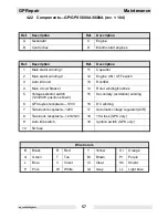
Page 57: ...ondary excitation winding 5 Voltage selector switch 120V 240V position shown 16 DC winding 6 GFI duplex receptacle 120V 17 Automatic voltage regulator AVR 7 Twist lock receptacle 120V 18 15A fuse GPS...

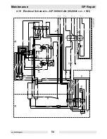
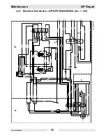
Page 58: ...Maintenance GP Repair wc_tx000546gb fm 54 4 19 Electrical Schematic GP 3800A CAN 0620041 rev 103...

Page 59: ...ing 5 Voltage selector switch 120 240V position shown 17 Automatic voltage regulator AVR 6 Duplex receptacle 120V 18 15A fuse GPS only 7 Twist lock receptacle 120V 19 Ignition switch GPS only 8 Twist...

Page 60: ...Maintenance GP Repair wc_tx000546gb fm 56 4 21 Electrical Schematic GP GPS 5600A 6600A rev 104...

Page 61: ...13 Rectifier 4 Main circuit breaker 14 Rotor winding brushes 5 Voltage selector switch 120 240V position shown 15 Secondary excitation winding 6 GFI duplex receptacle 120V 16 DC winding 7 Twist lock r...

Page 62: ...Maintenance GP Repair wc_tx000546gb fm 58 4 23 Electrical Schematic GP GPS 5600A 6600A rev 103...

Page 63: ...ing brushes 4 Main circuit breaker 15 Secondary excitation winding 5 Voltage selector switch 120 240V position shown 16 DC winding 6 Duplex receptacle 120V 17 Automatic voltage regulator AVR 7 Twist l...

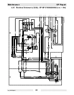
Page 64: ...Maintenance GP Repair wc_tx000546gb fm 60 4 25 Electrical Schematic CAN GP GPS 5600A 6600A rev 104...

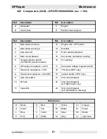
Page 65: ...condary excitation winding 5 Voltage selector switch 120V 240V position shown 16 DC winding 6 GFI duplex receptacle 120V 17 Automatic voltage regulator AVR 7 Twist lock receptacle 120V 18 15A fuse GPS...

Page 66: ...Maintenance GP Repair wc_tx000546gb fm 62 4 27 Electrical Schematic CAN GP GPS 5600A 6600A rev 103...

Page 67: ...ding 5 Voltage selector switch 120 240V position shown 17 Automatic voltage regulator AVR 6 Duplex receptacle 120V 18 15A fuse GPS only 7 Twist lock receptacle 120V 19 Ignition switch GPS only 8 Twist...

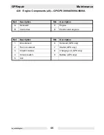
Page 68: ...Maintenance GP Repair wc_tx000546gb fm 64 4 29 Engine Schematic all GP GPS 3800A 5600A 6600A...

Page 69: ...0A Ref Description Ref Description A Generator C Engine B Control box D Electric start engines Ref Description Ref Description 1 Idle solenoid 6 Solenoid GPS only 2 Fuel cut solenoid 7 Starter GPS onl...

Page 70: ...Maintenance GP Repair wc_tx000546gb fm 66 Notes...

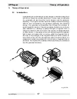
Page 71: ...ple of electromagnetic induction This principle states that when a coil of wire also referred to a winding is passed through a magnetic field a voltage is induced in the coil of wire The amount of vol...

Page 72: ...le voltage 120V in the stator The main winding is actually made up of two windings referred to as main winding 1 and main winding 2 The voltage induced in main winding 1 supplies the voltage to the le...

Page 73: ...tator winding via two sensing wires e Voltage induced through the excitation winding of the stator is rectified to DC by the voltage regulator The resulting DC voltage is sent to the field terminals b...

Page 74: ...ectifier where it is rectified to DC This DC voltage is then sent to the auto idle unit through the 5A fuse The auto idle unit senses the load on the generator via two wires connected to the main wind...

Page 75: ...e engine ON OFF switch With the engine ON OFF switch in the ON position power is diverted from the AAS to the capacitor and back to the DC winding As current flows the capacitor charges When the engin...

Page 76: ...malfunctioning voltage regulator 16 and problems with the brushes 13 and or the excitation winding 15 For a high voltage condition you ll need to rule out a malfunctioning voltage regulator and or pro...

Page 77: ...GP Repair Troubleshooting wc_tx000548gb fm 73 wc_gr003415 z y...

Page 78: ...more than 1 0 Ohm the wiring is faulty and must be repaired or replaced 6 3 Checking Resistance Conduct resistance checks when the engine is shut down Use the Ohm setting on your multimeter Most digit...

Page 79: ...rocess of determining the source of a problem with engine starting or machine operation Many of the tests involve live voltages and therefore should only be attempted by qualified personnel Detailed p...

Page 80: ...wchart 1B See Flowchart 1C Checking voltage at generator terminal strip Check voltage at back of generator between terminals R Y B G Checking voltage at generator plug Check voltage at back of generat...

Page 81: ...main 2 Br L main 1 Is the correct value measured for main winding 2 Replace the stator Yes No wc_gr003111 Is the correct value measured for main winding 1 Replace the stator Yes No Check resistance of...

Page 82: ...AC voltage setting on the multimeter measure the voltage between the wire with the yellow marking b and the wire with the red marking c There should be 120V 10 If zero 0 volts is measured it indicate...

Page 83: ...art the engine 6 9 3 Using the AC voltage setting on the multimeter measure the voltage between the red wire and the white There should be 120V 10 If zero 0 volts is measured it indicates a problem wi...

Page 84: ...cross the brown and blue wires Each generator size will have a different value Check the chart in the graphic for the correct values use a tolerance of 0 5 0 0 Ohm If the correct resistance is not mea...

Page 85: ...48gb fm 81 wc_gr003123 1000 200 20 2 200m F V A V COM GP 2500 47 5 GP 3800 47 0 GP 5600 60 5 GP 6600 64 8 1000 200 20 2 200m F V A V COM 1 d b c a f e 1 2 2 g 1 2 GP 2500 0 9 0 9 GP 3800 0 7 0 7 GP 56...

Page 86: ...breaker Check wiring to generator terminal strip Repair or replace wiring as needed Is correct voltage measured Yes No No Check outgoing voltage from main circuit breaker Replace the main circuit brea...

Page 87: ...GP Repair Troubleshooting wc_tx000548gb fm 83 Notes...

Page 88: ...heck the incoming voltage to the main circuit breaker a by measuring between each of the Hot terminals b wires 102 and 5 and ground On GP 2500A models measure between Hot terminals f and ground There...

Page 89: ...GP Repair Troubleshooting wc_tx000548gb fm 85 wc_gr003140 b a c d e V V GP 2500A f g 1000 200 20 2 200m F V A V COM 1000 200 20 2 200m F V A V COM...

Page 90: ...ain windings by measuring across R Y main 2 B G main 1 If you have recently worked on the generator be sure the wiring at the generator terminal strip is correct Is the correct value measured for main...

Page 91: ...rocedures 6 14 1 Stop the engine 6 14 2 Remove the two screws that secure the end cover to the generator and remove the end cover 6 14 3 Remove the screw a that secures the brush holder and remove the...

Page 92: ...erator and remove the end cover 6 15 3 Remove the plug a which connects the excitation winding to with the AVR On GP 2500A models remove plug b 6 15 4 Using the Ohms scale on your multimeter check the...

Page 93: ...GP Repair Troubleshooting wc_tx000548gb fm 89 wc_gr003127 b a 1000 200 20 2 200m F V A V COM GP 2500 2 3 GP 3800 1 1 GP 5600 0 9 GP 6600 0 9...

Page 94: ...remove the end cover 6 16 3 Disconnect the generator plug a 6 16 4 The two sensing wires are the brown and blue wires that share the same connector b as the wires for the DC winding disconnect this co...

Page 95: ...GP Repair Troubleshooting wc_tx000548gb fm 91 wc_gr003148 b c d a...

Page 96: ...usually connects There should be continuity If the first sensing wire does not have continuity replace the sta tor If the first sensing wire has continuity continue 6 17 5 The second sensing wire is r...

Page 97: ...eshooting wc_tx000548gb fm 93 If the second sensing wire circuit does not have continuity check the wiring through the various connectors and the VSS Repair or replace components as needed wc_gr003128...

Page 98: ...es are the brown and blue wires that share the same connector a as the wires for the DC winding disconnect this connector 6 18 5 Create two short jumper wires b and c each with one male spade and one...

Page 99: ...GP Repair Troubleshooting wc_tx000548gb fm 95 wc_gr003152 a 1000 200 20 2 200m F V A V COM V b c...

Page 100: ...he VSS is correctly wired before running the generator CAUTION Damage to the generator will occur if the VSS is incorrectly wired The VSS a selects the voltage mode setting of the generator Changing t...

Page 101: ...fm 97 wc_gr003134 2 1 3 12 9 6 5 4 7 8 11 10 Terminal 1 2 3 4 5 6 7 8 9 10 11 12 Brown 1 Brown 2 Brown 3 Gray 104 Brown 5 Gray 103 jumper to terminal 7 Brown 7 jumper to terminal 6 Blue 8 Jumper to te...

Page 102: ...g wires from the generator plug to the DC winding plug brown wire to brown wire blue to blue Then brown wire to blue blue wire to brown Checking sensing circuit Continue by checking the sensing wire c...

Page 103: ...solenoid is malfunctioning by measuring its coil s resistance and by checking action of plunger Replace the idle solenoid Check fuse replace if blown Check voltage at fuse There should be 20 2VDC Chec...

Page 104: ...easure the voltage between the two wires There should be 28 2VDC If 28 2VDC is measured the idle solenoid is receiving the correct voltage If the idle solenoid is receiving the correct voltage but is...

Page 105: ...GP Repair Troubleshooting wc_tx000548gb fm 101 wc_gr003130 b a c 1000 200 20 2 200m F V A V COM 1000 200 20 2 200m F V A V COM V 1000 200 20 2 200m F V A V COM V...

Page 106: ...onduct in one direction and not the other Check both upper terminals of the rectifier to the lower terminal of the rectifier in the same manner If the rectifier is malfunctioning replace it If the rec...

Page 107: ...GP Repair Troubleshooting wc_tx000548gb fm 103 wc_gr003131 1000 200 20 2 200m F V A V COM a b 1000 200 20 2 200m F V A V COM GP 2500 GP 3800 0 6 GP 5600 0 5 GP 6600 0 5 c d e...

Page 108: ...e switch lacks continuity replace it If the switch has continuity it should be functioning 6 24 4 Remove the plug from the back of the auto idle unit b 6 24 5 Start the generator 6 24 6 Check the volt...

Page 109: ...8 2VDC Is correct voltage measured No Yes Check the function of the main ON OFF switch Is the switch functioning No Yes Replace the main ON OFF switch Confirm the solenoid is malfunctioning by measuri...

Page 110: ...e was measured the AAS is malfunctioning replace it If the correct voltage was not measured continue 6 26 4 Remove the screws that secure the control panel to the generator 6 26 5 Check the continuity...

Page 111: ...GP Repair Troubleshooting wc_tx000548gb fm 107 wc_gr003133 b c 1000 200 20 2 200m F V A V COM V a 1000 200 20 2 200m F V A V COM d d F...

Page 112: ...Troubleshooting GP Repair wc_tx000548gb fm 108 Notes...

Page 113: ...tion refer to the Parts Book originally supplied with the unit If the original Parts Book has been lost a replacement may be ordered from Wacker Corporation When ordering a replacement Parts Book plea...

Page 114: ...the engine and remove the muffler and the inner muffler guard g from the engine Installation 7 5 6 When installing the muffler the inner muffler guard g will need to be positioned before installing th...

Page 115: ...GP Repair Disassembly Assembly Procedures wc_tx000549gb fm 111 wc_gr003136 c e f f h f g a b d...

Page 116: ...and remove the retaining bracket 7 6 5 Remove the four screws g that secure the tank h to the frame and lift the tank up and out of the frame Installation 7 6 6 When installing the fuel tank h screw i...

Page 117: ...GP Repair Disassembly Assembly Procedures wc_tx000549gb fm 113 wc_gr003137 a c gg c d c b d e f f h g...

Page 118: ...et Also remove the screw g that secures the other generator mounting leg and the muffler to the shock mount bracket 7 7 6 Remove the four long screws h that secure the stator cover to the engine and p...

Page 119: ...GP Repair Disassembly Assembly Procedures wc_tx000549gb fm 115 wc_gr003138 a d e c b f g i h...

Page 120: ...ill catch the rotor if it should drop off the tapered shaft during removal Also support the housing with a piece of wood or similar material 7 8 5 Insert into the hole in the shaft a headless M8 screw...

Page 121: ...GP Repair Disassembly Assembly Procedures wc_tx000549gb fm 117 wc_gr003139 d d c c e f a b...

Page 122: ...anel 7 9 5 Remove the three screws d that secure the muffler guard to the frame 7 9 6 Remove the nuts e that secure the shockmounts to the frame from underneath and pull the engine and muffler assembl...

Page 123: ...GP Repair Disassembly Assembly Procedures wc_tx000549gb fm 119 wc_gr003141 c a b d e f...

Page 124: ...Disassembly Assembly Procedures GP Repair wc_tx000549gb fm 120...

Page 125: ...5 ml 17380 50 ml Loctite 271 277 Hernon 427 Omnifit 1550 220M Red High strength for all threads up to 25 mm 1 Heat parts before disassembly Temp range 54 to 149 C 65 to 300 F 29312 5 ml 26685 10 ml 7...

Page 126: ...ts follow instructions on container The sealants listed are recommended for use on Wacker equipment TYPE Europe COLOR USAGE PART NO SIZE Loctite 496 Hernon 110 Omnifit Sicomet 7000 Clear Instant adhes...

Page 127: ...5 M4 2 9 26 4 1 36 4 9 43 7 9 32 3 M5 6 0 53 8 5 6 10 7 8 5 16 4 M6 10 7 14 10 17 13 10 5 M8 25 18 35 26 41 30 13 1 2 6 M10 49 36 69 51 83 61 17 11 16 8 M12 86 63 120 88 145 107 19 3 4 10 M14 135 99 1...

Page 128: ...8 2 5 22 3 5 31 4 7 42 9 11 32 9 64 No 10 3 6 32 5 1 45 6 8 60 3 8 5 32 1 4 8 1 6 12 9 16 12 7 16 3 32 5 16 18 13 26 19 33 24 13 1 2 1 4 3 8 31 23 45 33 58 43 9 16 5 16 7 16 50 37 71 52 94 69 16 5 8...

Page 129: ......
Page 130: ...02 0 Fax 49 0 89 3 54 02 3 90 Wacker Corporation P O Box 9007 Menomonee Falls WI 53052 9007 Tel 262 255 0500 Fax 262 255 0550 Tel 800 770 0957 Wacker Asia Pacific Operations Skyline Tower Suite 2303 2...

Reviews: