


Troubleshooting
GP Repair
wc_tx000548gb.fm
102
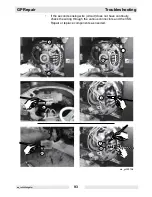
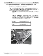
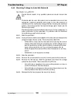
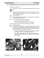
6.23 Checking Auto Idle Circuitry Between Generator and Fuse
See Graphic: wc_gr003131
Voltage may be prevented from reaching the 5A fuse by a faulty
rectifier or by a faulty DC winding. The auto idle circuit may also be
malfunctioning due to faulty sensing wires. To check the circuit, carry
out the following procedures:
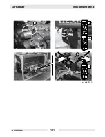
6.23.1 Stop the generator.
6.23.2 Remove the two screws which secure the end cover to the generator
and remove the end cover.
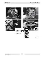
6.23.3 To check the rectifier
(a)
, remove the connector plug from the rectifier.
Use the diode scale on your multimeter. Probe the top terminal with
one lead and the bottom terminal with the other. Then, reverse the
leads and conduct the test again. The rectifier should conduct in one
direction and not the other. Check both upper terminals of the rectifier
to the lower terminal of the rectifier in the same manner.
•
If the rectifier is malfunctioning, replace it.
•
If the rectifier is functioning, continue.
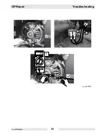
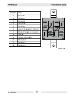
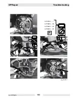
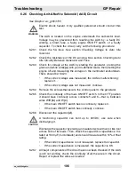
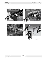
6.23.4 Remove the plug
(b)
from the stator.
6.23.5 Using the Ohms scale on your multimeter, check the resistance of the
DC winding. Each generator size will have a different value for the
winding resistance. Check the chart in the graphic for the correct
values—use a tolerance of +0.5/-0.0 Ohms.
•
If the correct amount of resistance was not measured, replace
the stator.
•
If the correct amount of resistance was measured, the DC wind-
ing is OK; continue.
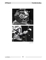
6.23.6 Remove the screws which secure the control panel to the generator.
6.23.7 Check that the sensing wires are running through the ammeter
(c)
of
the auto idle unit.
6.23.8 Check the continuity of the sensing wires
(d)
from the auto idle unit
through to the generator terminal strip
(e)
.
Summary of Contents for GP 3800A
Page 2: ......
Page 13: ...GP Repair Safety Information wc_si000169gb fm 9 1 4 Label Locations GND 88897...
Page 25: ...GP Repair Technical Data wc_td000169gb fm 21 Notes...
Page 50: ...Maintenance GP Repair wc_tx000546gb fm 46 4 11 Electrical Schematic GP 2500A...
Page 52: ...Maintenance GP Repair wc_tx000546gb fm 48 4 13 Electrical Schematic GP 3800A 0620010 rev 104...
Page 54: ...Maintenance GP Repair wc_tx000546gb fm 50 4 15 Electrical Schematic GP 3800A 0620010 rev 103...
Page 60: ...Maintenance GP Repair wc_tx000546gb fm 56 4 21 Electrical Schematic GP GPS 5600A 6600A rev 104...
Page 62: ...Maintenance GP Repair wc_tx000546gb fm 58 4 23 Electrical Schematic GP GPS 5600A 6600A rev 103...
Page 68: ...Maintenance GP Repair wc_tx000546gb fm 64 4 29 Engine Schematic all GP GPS 3800A 5600A 6600A...
Page 70: ...Maintenance GP Repair wc_tx000546gb fm 66 Notes...
Page 77: ...GP Repair Troubleshooting wc_tx000548gb fm 73 wc_gr003415 z y...
Page 87: ...GP Repair Troubleshooting wc_tx000548gb fm 83 Notes...
Page 95: ...GP Repair Troubleshooting wc_tx000548gb fm 91 wc_gr003148 b c d a...
Page 112: ...Troubleshooting GP Repair wc_tx000548gb fm 108 Notes...
Page 115: ...GP Repair Disassembly Assembly Procedures wc_tx000549gb fm 111 wc_gr003136 c e f f h f g a b d...
Page 119: ...GP Repair Disassembly Assembly Procedures wc_tx000549gb fm 115 wc_gr003138 a d e c b f g i h...
Page 121: ...GP Repair Disassembly Assembly Procedures wc_tx000549gb fm 117 wc_gr003139 d d c c e f a b...
Page 123: ...GP Repair Disassembly Assembly Procedures wc_tx000549gb fm 119 wc_gr003141 c a b d e f...
Page 124: ...Disassembly Assembly Procedures GP Repair wc_tx000549gb fm 120...
Page 129: ......


