


5-20
BA EZ17 en* 1.1 * ez17b510.fm
5 Operation
.
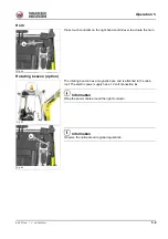
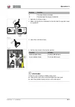
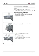
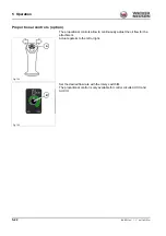
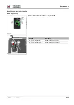
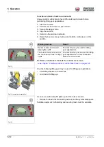
1. Raise the control lever base.
2. Make sure that the lever
A
located to the left under the operator’s seat
is in position
1
.
3. Lower the control lever base.
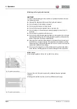
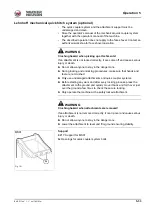
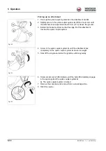
4. Using the boom and dozer blade, raise the vehicle so that it is no
longer in contact with the ground and no foreign body is in the travel
gear during extension or retraction.
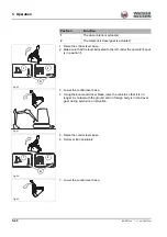
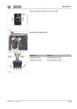
5. Raise the control lever base.
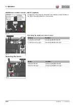
6. Set lever
A
in position
2
.
7. Lower the control lever base.
Position
Function
1
The dozer blade is actuated.
2
The telescopic travel gear is actuated.
Fig. 96
1
2
A
Fig. 97
Fig. 98
1
2
A
Fig. 99
Summary of Contents for E13-01
Page 6: ...EG 2 BA EZ17 en 1 1 ez17konf fm Declaration of conformity Notes...
Page 36: ...2 22 BA EZ17 en 1 1 Safety_01_0 fm 2 Safety Notes...
Page 45: ...BA EZ17 en 1 1 ez17e300 fm 3 9 Introduction 3 Warning labels...
Page 50: ...3 14 BA EZ17 en 1 1 ez17e300 fm 3 Introduction Labels...
Page 90: ...4 36 BA EZ17 en 1 1 ez17i400 fm 4 Putting into operation Notes...
Page 158: ...5 68 BA EZ17 en 1 1 ez17b510 fm 5 Operation Notes...
Page 216: ...7 50 BA EZ17 en 1 1 ez17w710 fm 7 Maintenance Notes...
Page 220: ...8 4 BA EZ17 en 1 1 ez17b800 fm 8 Malfunctions Notes...
Page 244: ...9 24 BA EZ17 en 1 1 ez17t900 fm 9 Technical data Dimensions Fig 243...
Page 246: ...9 26 BA EZ17 en 1 1 ez17t900 fm 9 Technical data Notes...