


47
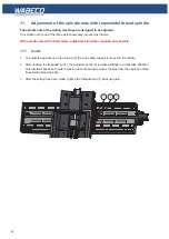
11. Adjustment of the spindle nuts with trapezoidal thread spindle
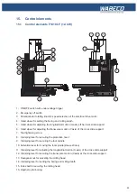
11.2 Y-axis
1. To adjust the spindle nut of the Y-axis (5), either unscrew the bellows (7) on the upper skid or care-
fully tip the machine backwards to gain access to work from the bottom.
2. After undoing the threaded pin (4), the adjustment nut (6) is rotated slightly in a clockwise direction.
This rotation causes both nuts to tension each other and removes the play from the operation of the
trapezoidal thread spindle.
3. After the setting has been made, tighten the threaded pin (4) back up again.
4. Install the bellows (7) and tighten screws (8).
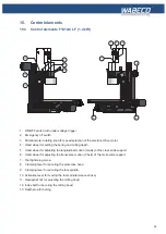
11.3 Z-axis
1. To adjust the spindle nut in the Z-axis (2) unscrew the cover plate on the back of the Z-column.
2. After undoing the threaded pin (1) the adjustment nut (3) is rotated slightly in a clockwise direction.
This rotation causes both nuts to tension each other and removes the play from the operation of the
trapezoidal thread spindle.
3. After the setting has been made, tighten the threaded pin (1) back up again.
8
4
5
6
7
2
1
3
Summary of Contents for F1410 LF
Page 41: ...41 7 Fitting and removing the tools 42 6 Spannen und Ausdrücken der Werkzeuge 1 2 3 4 5 ...
Page 98: ...98 16 Drawings and legends 16 12 Spindle Z axis with ball screws 16 12 1 F1410 LF F1410 LF hs ...
Page 126: ...126 16 Drawings and legends 16 22 Support arm for control panel 1 2 3 4 5 6 8 9 5 4 7 9 8 ...


