142
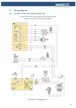
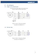
17. Circuit diagram
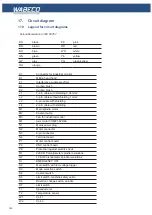
17.9 Legend for circuit diagrams
BK
black
PK
pink
BN
brown
RD
red
BU
blue
WH
white
GN
green
YE
yellow
GY
gray
YG
green/yellow
OG
orange
A1
Connector for industrial monitor
B1
Milling head hood
F1
Interference suppressor filter
K1
Carbon brush
K2
Carbon brush
L1
7- pin cable with shielding 0.34 mm2
L2
3- pin cable without shielding 1 mm2
L3
6-pin cable with shielding
L4
2- pin cable with shielding
M1
Main spindle motor
M2
Coolant pump
M3
Fan for industrial monitor
M4
Axis motor 3H8221-624/6A
N1
Mains power plug
N2
Motor connector
N3
9-pin connector
N4
Terminal board
P1
Motor control board
P2
CNC control board
PE
Protection against electric shock
R1
220 KΩ Potentiometer spindle revolutions
R2
10 KΩ Potentiometer spindle revolutions
S1
EMERGENCY OFF
S2
Main switch with low voltage trigger
S3
Mode selection switch
S4
Coolant switch
S5
Limit switch, machine safety cabin
S6
Direction change switch, spindle
S7
Limit switch
T1
Speedometer
T2
Temperature sensor
W1
Coil 1
W2
Coil 2
Color-abbreviation to IEC 60757
Summary of Contents for F1410 LF
Page 41: ...41 7 Fitting and removing the tools 42 6 Spannen und Ausdrücken der Werkzeuge 1 2 3 4 5 ...
Page 98: ...98 16 Drawings and legends 16 12 Spindle Z axis with ball screws 16 12 1 F1410 LF F1410 LF hs ...
Page 126: ...126 16 Drawings and legends 16 22 Support arm for control panel 1 2 3 4 5 6 8 9 5 4 7 9 8 ...


