


Page 17 of 48
PAM-199-P
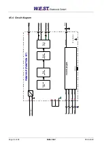
4.4
Control of two throttle and / or pressure valves (196)
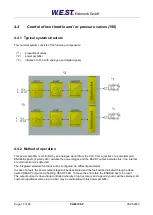
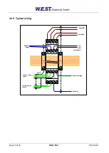
4.4.1 Typical system structure
This minimal system consists of the following components:
(*1)
proportional valves
(*2)
power amplifier
(*3)
interface to PLC with analogue and digital signals
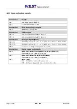
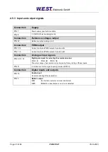
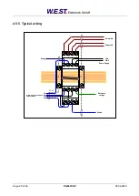
4.4.2 Method of operation
This power amplifier is controlled by an analogue signal (from the PLC, from a joystick or a potentiometer).
ENABLE signals (typically 24V) activate the power stages and the READY output indicates this, if no internal
or external error was detected.
The integrated standard functions will be configured via different parameters.
In case of a fault, the power output stage will be deactivated and the fault will be indicated through a deac-
tivated READY output and a flashing READY LED. To leave the error state the ENABLE has to be reset.
The output current is closed loop controlled whereby a high accuracy and a good dynamic will be obtained. All
custom proportional valves (up to 2.6A) may be controlled with this power amplifier.