


Page 10 of 48
PAM-199-P
3.2
Commissioning
Step
Task
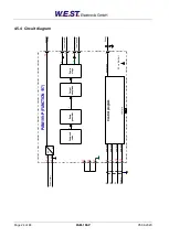
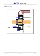
Installation
Install the device in accordance with the circuit diagram. Ensure it is wired correctly
and that the signals are well shielded. The device must be installed in a protective
housing (control cabinet or similar).
Switching on for the first
time
Ensure that no unwanted movement is possible in the drive (e.g. switch off the
hydraulics). Connect an ammeter and check the current consumed by the device. If
it is higher than specified, there is an error in the wiring. Switch the device off imme-
diately and check the wiring.
Setting up communication
Once the power input is correct the PC (notebook) should be connected to the
serial interface. Please see the WPC-300 program documentation for how to set up
communication.
Further commissioning and diagnosis are supported by the operating software.
Pre-parameterization
Now set up the following parameters (with reference to the system design and circuit
diagrams):
The nominal output CURRENT and the typical valve parameters such as DITHER
and MIN/MAX.
Pre-parameterization is necessary to minimize the risk of uncontrolled movements.
Control signal
Check the control signal with an amp meter. The control signal (the current of the
solenoid) is within the range of 0... 2.6A. In the actual status it should show approxi-
mately 0 A.
ATTENTION!
You can monitor the current of the solenoids also in the WPC-300 pro-
gram.
Switching on the hydrau-
lics
The hydraulics can now be switched on. The module is not yet generating a signal.
Drives should be at a standstill or drift slightly (leave its position at a slow speed) if it
is a proportional valve.
Activating ENABLE
CAUTION!
The drive can now leave its position and move to an end position with full
speed or the pressure can reach maximum. Take safety measures to prevent per-
sonal injury and damage.