7
8
OIMM – VENTUS PRO
The outlet condensate connections, led outside the AHU’s casing are assembled in the drain plates of coolers,
counter–flow heat exchangers (the diameter of drain pan connection pipe is 32mm).
To avoid damage drain pipe of the counter-flow heat exchanger section during transportation, they are not
installed and attached separately in the package.
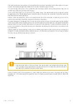
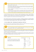
To mount the drain pipe one should unscrew the drilling screws and disassembly header connection glands
(magnification (1) in the the below figure), install the pipe on the drain pan connection inside the casing and
assembly bach the header glands (2).
Siphons, which are designed to drain out condensed water from the exchangers at different pressure of the
section and environment, should be connected to the drain connections.
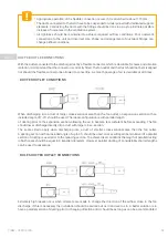
For proper drainage of condensate from the unit, the siphon on the drain pan connection pipe must be installed
in the AHU sections, where negative pressure occurs. Drain siphons or siphon parts are not supplied as standard
delivery. There is no need to apply drain siphons in section with overpressure. In order to minimize air blow–by,
you can use a siphon on the system draining out condensate, assembling the siphon made in accordance with
fig. 5 and table 1.
Siphons usable „H” height depends on the pressure difference between the AHU section, where condensate is
drained from during operation and the ambient pressure. „H” dimension is provided in mm and must be higher
than the pressure difference expressed in mmH2O.
If the air handling unit is to be installed in a place where low vibration and noise is required such as hotels,
hospitals etc. it is recommended to install the unit on a floating concrete base, around which is filled with
Styrofoam
»
FITTINGS
!
First attach the bolts on the base frame, then section bolts and tighten both with the same
order and same torque gradually. Do not use excessive force to align the sections, because it
may deform the aluminum framework and casing.
!


