29
Figure 4
‑
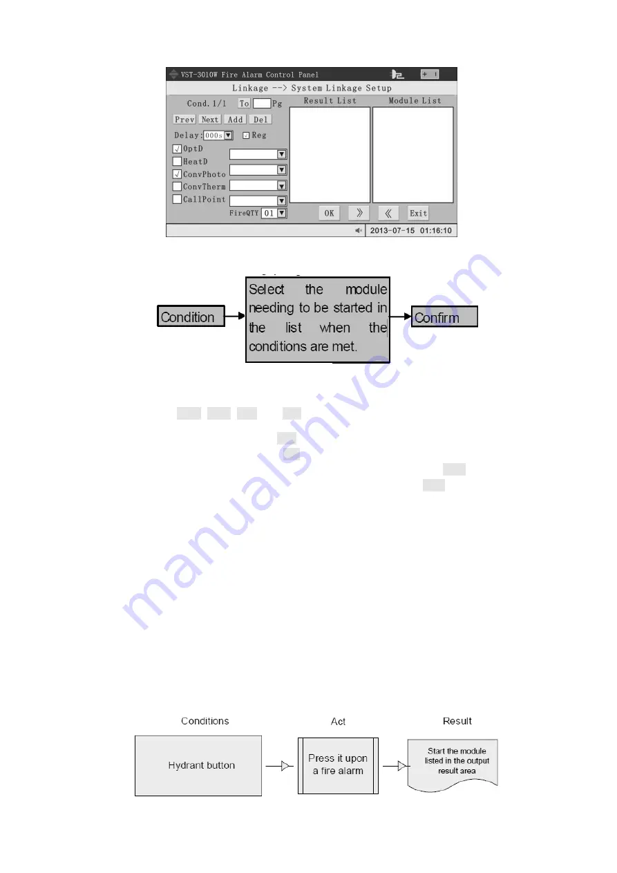
33 System linkage setup interface
The setup interface is divided into 3 areas: condition setting area, result output area and
target selection area
Each page (i.e. display of the entire screen) corresponds to a linkage condition. The setup
flow of a linkage condition is as follows:
Step 1: condition setting
Four buttons (P
REV
, N
EXT
, A
DD
and D
EL
) and a text input box are set above the condition
setting area, which are used for inquiring, adding or deleting linkage conditions.
Adding a linkage condition: click on Add button
Deleting a linkage condition: click on Del button
Viewing or editing the linkage condition on the previous page: click on Prev
Viewing or editing the linkage condition on the next page: click on Next
Viewing or editing a certain linkage condition: enter serial number of the linkage condition
into the text box before “Pg”, enter or click on To button
The system will display another linkage condition when any of the above operations is
carried out. “Cond. 1/3” at top left corner of the display means currently there are 3 system
linkage conditions and the first one is displayed at the moment. If the linkage conditions are
large in number, enter into the page number to skip. If the corresponding modules of a linkage
condition are multiple, the page switching may take 2-5s.
The edit area for current linkage condition is set below the condition setting area.
“Delay”: select the time interval between condition satisfied and action of module;
“Reg”: check the option to activate the linkage action on this page;
“Input type”: composed of check box at the left side and drop-down box at the right side. The
relation between input type is “or”;
“Fire QTY”: the number of fires required to satisfy the conditions. For example, 01 means
the conditions are satisfied when the alarms is generated at any 1 point. The system can
achieve composite functions of multiple arbitrary alarms and the maximum composite number is
99.
Therefore, the linkage conditions in the above figure are as follows:


