background image

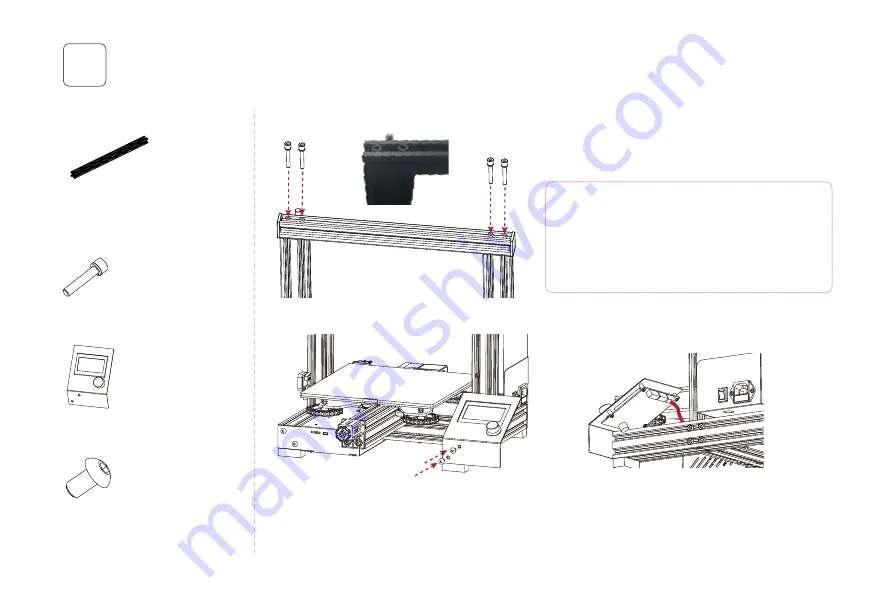
Install the gantry profile and screen kit

7

Gantry profile *1

1. Fix the profile on the upper end of the gantry with four 

    M5x25 screws.

2. 

3. 

Hexagon socket head spring

washer combination screw

M5x25 *4

M5x25

M5x25

M5x8

14

Connect the screen cable to EXP3 port of the screen kit

(as shown).

Screen kit *1

Hexagon socket button 

head screws M5x8 *2

Lock the screen kit onto printer base side using two 

M5x8 screws.

安装顶部型材和屏幕组件

顶部型材 *1 

内六角圆柱头弹垫组合螺钉

M5x25 *4

内六角平圆头螺钉M5x8 *2

显示屏组件 *1

用4颗M5x25螺钉将顶部型材安装在两侧Z轴型材的上方。

注意:顶部型材的沉头孔朝上,4颗螺钉头部藏在型材沉孔里面,

螺钉安装好后与型材齐平。

将屏幕排线与屏幕组件的EXP3端口连接(如图所示)。

用2颗M5x8螺钉将屏幕组件安装到设备底座右侧。

Note: Make the counterbores within the profile and 

face upwards. Four cap screws are slotted in the 

counterbores, please tighten the screws down to the 

profile edge.

Summary of Contents for Aquila C2

Page 1: ...nual Aquila C2 V1 2 1 20210731 Note Each printer is tested before leaving factory It is normal if there are some residues in extruder or some tiny scratches on the build plate It won t a ect the print...

Page 2: ...products For your convenience please read the manual carefully before using it Operate the printer accordingly Voxelab team is always at your service contact us at any time if you need any assistance...

Page 3: ...ter on a shaking place It may a ect the printing quality Children and untrained personnel are not allowed to operate the printer alone Operate the printer in a well ventilated environment Some materia...

Page 4: ...sive block Z 1 2 3 4 5 6 7 X axis tensioner X Power switch and socket Screen Knob switch Voltage regulator Power supply Machine base 8 9 10 11 12 13 14 Y axis limit sensor Y Y axis motor Y E axis moto...

Page 5: ...e temperature Resume printing fuction Filament sensor Dual z axis screws Z Language switch Computer operating system Print speed Voxelab Aquila C2 220 220 250 mm FDM 1 0 05 mm 0 4 mm Standard 0 4 mm 0...

Page 6: ...xtruder kit 1 Z axis passive block 1 X axis tensioner 1 Z axis motor kit 1 X axis limit sensor kit 1 XE axis kit 1 Z axis pro le left 1 Z axis pro le right 1 Gantry pro le 1 X axis pro le 1 T shaped s...

Page 7: ...20 2 Hexagon socket head spring washer combination screw M5x25 5 M4 T nuts 2 Hexagon socket head cap screws M4x8 2 Hexagon socket head cap screw M4x20 2 Nozzle 1 Filament 1 Hexagon socket button head...

Page 8: ...ase 1 1 Step Use four M5x45 screws to x Z axis with the base Z axis pro le right 1 Hexagon socket head spring washer combination screw M5x45 4 M5x45 Z axis pro le left 1 07 Installation video can be f...

Page 9: ...or kit on the pro le as shown below Z axis motor kit 1 T shaped screw rod 1 Hexagon socket countersunk head screw M4x20 2 Step 2 Install the power supply kit on Z axis pro le with two hexagon socket h...

Page 10: ...ten the M6 Pneumatic joint by using open end wrench And x the XE axis kit with two M5x14 screws XE axis kit 1 X axis pro le 1 M6 Pneumatic joint 1 Open end wrench 1 Hexagon socket button head screws M...

Page 11: ...kit The belt is on the top of the pro le and under the V wheel when pushing extruder kit into the middle Extruder kit 1 The highlighted red stripe is the synchronous belt Install Z axis passive block...

Page 12: ...ock it with two M5x14 screws on both sides of the Z axis passive block 2 Insert the synchronous belt into the tensioner block Hexagon socket head cap screw M4x8 2 M5x14 Hexagon socket button head scre...

Page 13: ...Insert the synchronous belt buckle into the sheet metal slot at the back of the extruder and tighten X axis tensioner completely 5 Lock the X axis limit sensor kit on the XE axis kit with two M4x8 sc...

Page 14: ...s best when the extruder able to touch the X axis limit sensor and synchronous belt in a proper elasticity Take the fth step assembled components Take the second step assembled components Back Front A...

Page 15: ...M5x25 M5x8 14 Connect the screen cable to EXP3 port of the screen kit as shown Screen kit 1 Hexagon socket button head screws M5x8 2 Lock the screen kit onto printer base side using two M5x8 screws 1...

Page 16: ...e spool holder on the rack and x on the pro le with screws as shown then place the 2020 pro le cover on both side Material rack 1 Material pipe and nut 1 2020 pro le cover 2 T nuts 2 Hexagon socket bu...

Page 17: ...or 6 4 X X 4 Connect the yellow labeled cable with Z on 3 pin port to Z axis limit sensor 3 Z Z 5 Connect the yellow labeled cable with Z on 6 pin port to Z axis motor 6 Z Z 6 Pass the left power cabl...

Page 18: ...eadiness of the build plate before leveling If the build plate is unsteady please use open end wrench to adjust the V wheel to steady it Press knob select Motion Auto Home rst to ensure the extruder i...

Page 19: ...and the printing platform to about 0 1 mm Thickness of a piece of A4 paper 2 We can use a piece of A4 paper to assist in leveling so that the nozzle only scratches on the A4 paper Adjust the four leve...

Page 20: ...ation is only for reference the actual UI may be di erent 19 Press knob select Temperature Preheat PLA ABS Press knob select Temperature Nozzle rotate the knob to adjust the nozzle temperature 1 2 Tem...

Page 21: ...l lament back and forth to see if extrusion pressure is too high or too low adjust the screw on the force arm if the pressure is improper 3 Insert laments into lament tube press the knob select Load F...

Page 22: ...nt out from the feeding assembly repeat the load process 2 To replace lament during the printing process rotate the knob to slow the printing speed to 10 and cut o the lament nearby the feeding assemb...

Page 23: ...nd install it to your computer Open the software load the stl le for slicing then saved the sliced le to the TF card 1 Ensure that the build plate has been leveled before printing 2 Ensure that the la...

Page 24: ...e distance is improper please press knob and select Tune Babystep Z to perform the Z axis o set When the o set value is positive the nozzle and the build plate get farther when the o set value is nega...

Page 25: ...Turbofan port Mainboard cooling fan X axis limit sensor port Y axis limit sensor port Z axis limit sensor port Nozzle thermistor port Micro USB port Screen port Hotbed thermistor port Power port Y axi...

Page 26: ...heck the tension of synchronous belt and make it neither too loose nor too tight When synchronous belt working well please check the transmission ratio Turn up the transmission ratio if the size gets...

Page 27: ...he temperature is shown abnormal it is in the reason of thermistor Please replace the thermistor and try again 2 If the temperature is shown normal it may be in the reason of heating cable Please repl...

Page 28: ...s stuck if it is please clean it up Q What if o set occurs on the printed model A 1 Check the tightness of the synchronous belt and ensure it is correctly installed 2 Slice the model again 3 Reduce pr...

Page 29: ...gether with the printer or download this form from www voxelab3dp com ll in this form and mail it to support voxelab3dp com After sales service shall not be provided without this form Please contact y...

Page 30: ...not be con rmed Damage s caused by improperly or incorrectly performed modi cations alterations or repair Damage s caused by operation under improper environment damp wet or other extreme weather Exte...

Page 31: ...1 Voxelab 3D 12 FFF 3D 3 2 Voxelab 3 4 Voxelab Voxelab U TF USB Voxelab Voxelab 3D Voxelab SAC20200804...

Page 32: ...District Jinhua Zhejiang China Physical objects and nal images might be distinct from the user manual due to di erences between printer models Voxelab reserves nal explanation rights Voxelab Voxelab v...

Reviews: