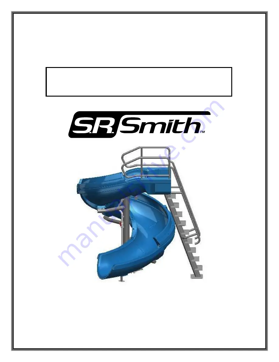
background image

06-199 

S.R. SMITH, LLC 2008


AUG13 


VORTEX  


CORPORATE HEADQUARTERS 

WESTERN SALES AND MANUFACTURING PLANT 

P.O. Box 400 

••••

 1017 SW Berg Parkway 

Canby, Oregon 97013 

Phone: (503) 266-2231 

••••

 Fax: (503) 266-4334 

www.srsmith.com 


ASSEMBLY AND INSTALLATION 

INSTRUCTIONS 


Summary of Contents for S.R.Smith

Page 1: ... 2008 AUG13 VORTEX CORPORATE HEADQUARTERS WESTERN SALES AND MANUFACTURING PLANT P O Box 400 1017 SW Berg Parkway Canby Oregon 97013 Phone 503 266 2231 Fax 503 266 4334 www srsmith com ASSEMBLY AND INSTALLATION INSTRUCTIONS ...

Page 2: ...S LAKES PONDS RIVERS ETC PROPER ASSEMBLY INSTALLATION USE AND SUPERVISION IS ESSENTIAL FOR PROPER OPERATION AND TO REDUCE THE RISK OF SERIOUS INJURY OR DEATH ALL NATIONAL AND LOCAL BUILDING CODES MUST BE FOLLOWED THIS INCLUDES ANY APPLICABLE REQUIREMENTS FOR SIZE OF CONCRETE FOOTING OVERALL HEIGHT OF SLIDE AND BONDING OR ELECTRICAL CODES CHECK INSIDE ALL BOXES AND PACKAGING MATERIALS FOR PARTS BEF...

Page 3: ...HOWN IN FIGURES 33 34 AND 36 ON PAGES 38 AND 39 MAINTENANCE INSTRUCTIONS 1 PERIODICALLY INSPECT THE VORTEX TO ASSURE THERE ARE NO WORN PARTS AND THAT ALL HARDWARE IS PROPERLY TIGHTENED REPLACE ANY HARDWARE WHICH EXHIBITS RUST OR CORROSION 2 ALL SLIDE COMPONENTS REQUIRE PERIODIC MAINTENANCE CLEAN COMPONENTS WITH A COTTON CLOTH AND A NON ABRASIVE SOAP AND WATER AVOID HARSH CHEMICALS AND DISINFECTANT...

Page 4: ...4 VORTEX SLIDE WITH STAIRS LAYOUT FIGURE 1 ...

Page 5: ...5 VORTEX SLIDE WITH LADDER LAYOUT FIGURE 2 ...

Page 6: ...4 BHCS S S 8 ea 12 5 515 3 8 x 5 BHCS S S 4 ea 15 5 524 SS x 5 HHCS S S 5 ea 16 VULKEM 116 VULKEM GRAY SEALANT 17 05 14 132 x 1 3 8 FLAT WASHER S S 10 ea 18 05 14 115 LOCK WASHER S S 17 ea 20 05 14 116 HEX NUT S S 5 ea 21 05 14 107 3 8 x 1 FLAT WASHER S S 18 ea 22 05 616 NYLON WASHER 22 ea 23 05 32 111 3 8 NYLON WASHER 22 ea 24 5 145 3 8 FLAT WASHER S S 48 ea 25 5 151 3 8 LOCK WASHER S S 24 ea 26 ...

Page 7: ...e 14 Anti seize 15 Saw to cut PVC pipe 16 Knife 17 Level 18 Hammer 19 8 step ladder 20 Rubber Mallet Gasket Installation The gasket material has been installed at the factory however additional gasket has been provided in case any gasket has fallen off during shipping If gasket installation is required follow the instructions below Apply gasket in the required locations as shown in the figures bel...

Page 8: ... The required hardware is as follows 13 x 5 Hex Head Cap Screw 15 Flat Washer 17 Nylon Washer 22 and Nylon Washer 22 Flat Washer 17 Lock Washer 18 Hex Nut 20 on the other side of the support It is important not to tighten the hardware at this point ANTI SEIZE NEEDS TO BE USED ON ALL BOLTS and should be applied to the threading before attempting to place the nut on the bolt 2 The image on the right...

Page 9: ...follows 3 8 16 x 4 Button Head Cap Screw S S 11 3 8 Flat Washer 24 3 8 Flat Washer 24 3 8 Lock Washer 25 3 8 Hex Nut S S 26 Tighten the hardware until snug Note Be sure to apply anti seize to all fasteners to prevent galling 4 Next flip over the two connected pieces of the runway Place the Exit Support 6 under the Exit Flume 3 as shown in Figure 7 Use the following hardware to attach the exit supp...

Page 10: ...e marked locations for the exit support The holes in the main support tube flange may be used as a template for drilling the 1 2 diameter X 2 1 4 deep holes Follow the instruction on page 23 and install the concrete wedge anchors for the exit support and the main tube support 6 Place the assembled Exit Flume 3 and Runway Section 2 over the first Branch Arm 6 Attach the slide sections to the first ...

Page 11: ...s follows 3 8 X 5 5 Hex Bolt 8 3 8 Flat Washer 21 3 8 Nylon Washer 23 3 8 Flat Washer 21 3 8 Lock Washer 25 and a 3 8 Hex Nut 26 It is important that the Nylon Washer 23 be placed against the metal branch arm bracket This process should be repeated for the three remaining Runway Sections Remember that order of assembly is important The end of each runway section is labeled and must be assembled to...

Page 12: ... the threaded inserts in the entrance section The hardware required includes 3 8 16 x 3 5 Button Head Cap Screw S S 10 3 8 Lock Washer S S 24 3 8 Flat Washer S S 25 and a 3 8 Nylon Washer 23 Note Be sure to apply anti seize to all fasteners to prevent galling After you have started all of these bolts you should go back through and tighten all of the fasteners installed up to this point Apply the 5...

Page 13: ...8 x 5 BHCS S S 18 ea 13 5 518 3 8 x 6 BHCS S S 2 ea 14 5 516 3 8 x 8 5 HHCS S S 4 ea 21 05 14 107 3 8 x 1 FLAT WASHER S S 12 ea 24 5 145 3 8 FLAT WASHER S S 60 ea 25 5 151 3 8 LOCK WASHER S S 30 ea 26 5 139 3 8 HEX NUT S S 30 ea 27 05 626 3 8 RUBBER WASHER 4 ea 30 1 300 2 SCH 40 PVC SPACER 2 75 12 ea 2 11 12 13 14 21 24 25 26 27 30 ...

Page 14: ...s follows 3 8 16 x 4 Button Head Cap Screw S S 11 3 8 Flat Washer S S 24 3 8 Flat Washer S S 24 3 8 Lock Washer S S 25 3 8 Hex Nut S S 26 Next finish fastening the parts together as shown in Figure 12 Detail B The hardware required for this step is as follows 3 8 16 x 5 Button Head Cap Screw 12 and a 3 8 Flat Washer S S 21 3 8 Flat Washer 21 3 8 Lock Washer 25 3 8 Hex Nut 26 Follow the same proced...

Page 15: ...8 Flat Washer S S 24 3 8 Lock Washer S S 25 3 8 Hex Nut S S 26 Next working from the top to bottom fasten the flumes together along the outside edge as shown in Figure 13 Detail A The required hardware is as follows a 3 8 16 x 5 Button Head Cap Screw S S 12 3 8 Flat Washer S S 24 3 8 Flat Washer S S 24 Sch 40 PVC Spacer 3 25 30 3 8 Flat Washer S S 24 3 8 Lock Washer S S 25 3 8 Hex Nut S S 26 Tight...

Page 16: ... S S 14 3 8 Flat Washer S S 24 3 8 Rubber Washer 27 3 8 Flat Washer S S 24 3 8 Lock Washer S S 25 3 8 Hex Nut S S 26 There are four locations where this step is repeated After you have started all of these bolts you should go back through and tighten all of the fasteners installed up to this point Note Be sure to apply anti seize to all fasteners to prevent galling FIGURE 14 14 27 24 26 25 ...

Page 17: ...ER BRACKET S S 2 ea 11 5 513 3 8 x 4 5 BHCS S S 6 ea 12 5 515 3 8 x 5 BHCS S S 16 ea 61 5 514 3 8 x 75 BHCS S S 4 ea 23 05 32 111 3 8 NYLON WASHER 6 ea 24 5 145 3 8 FLAT WASHER S S 60 ea 25 5 151 3 8 LOCK WASHER S S 22 ea 26 5 139 3 8 HEX NUT S S 22 ea 30 1 300 2 SCH 40 PVC SPACER 2 75 12 ea 59 11 12 60 61 24 25 26 30 23 ...

Page 18: ...own in Figure 15 Detail A The hardware required for the two side locations is as follows 3 8 16 x 4 5 Button Head Cap Screw S S 11 3 8 Flat Washer S S 24 3 8 Flat Washer S S 24 3 8 Lock Washer S S 25 3 8 Hex Nut S S 26 Follow the same procedure to finish assembling the remaining two sections together Note Be sure to apply anti seize to all fasteners to prevent galling 25 26 FIGURE 15 24 11 ...

Page 19: ... through the bottom flume and the bracket use a 3 8 16 x 5 Button Head Cap Screw S S 12 3 8 Flat Washer S S 24 3 8 Flat Washer S S 24 3 8 Lock Washer S S 25 3 8 Hex Nut S S 26 Next through the open flume and the bracket use a 3 8 16 x 75 Button Head Cap Screw S S 61 3 8 Nylon Washer 23 and a 3 8 Flat Washer S S 24 Do not fully tighten any of the hardware until all of the hardware has been assemble...

Page 20: ...t Washer S S 24 3 8 Flat Washer S S 24 Sch 40 PVC Spacer 3 25 30 3 8 Flat Washer S S 24 3 8 Lock Washer S S 25 3 8 Hex Nut S S 26 Tighten the hardware until the gap in the joint is closed After you have started all of these bolts you should go back through and tighten all of the fasteners installed up to this point Note Be sure to apply anti seize to all fasteners to prevent galling FIGURE 17 12 2...

Page 21: ...ea 33 05 625 5 16 NYLON WASHER 50 ea 34 5 306 5 16 LOCK WASHER S S 8 ea 35 5 303 5 16 FLAT WASHER S S 50 ea 36 2022650 5 16 HEX NUT S S 8 ea 37 05 233 SPACER 14 ea 38 8 301 OUTSIDE STAIR BRACKET 3 ea 39 8 300 INSIDE STAIR BRACKET 3 ea 40 8 303 BOTTOM OUTSIDE STAIR BRACKET 1 ea 41 8 302 BOTTOM INSIDE STAIR BRACKET 1 ea 19 8 306 STEP BRACKET ANCHOR 1 ea 42 6 695 REAR PLATFORM STEP 3 ea 43 6 694 FORW...

Page 22: ...ter X 2 25 deep holes for the concrete anchors Follow the instructions on page 30 for inserting the concrete anchors into the deck Place the support over the concrete anchors and against the entrance section of the slide Attach the following hardware to the concrete anchors but do not fully tighten 1 2 Nylon Washer 22 1 2 Flat Washer 17 1 2 Lock Washer 18 and a 1 2 13 Hex Nut 20 Next place the req...

Page 23: ...2 Flat Washer 17 1 2 Lock Washer 18 and a 1 2 Hex Nut 20 see Detail A Do not fully tighten yet After all hardware has been attached tighten each bolt securely Second place the Inside Stair Bracket 39 on the opposite side and repeat the steps to mount it securely to the slide Add another set of inside and outside brackets and repeat the hardware steps to attach them The next outside bracket should ...

Page 24: ...l B The required hardware is as follows 1 2 x 1 5 Hex Head Bolt 31 1 2 Flat Washer 17 1 2 Nylon Washer 22 1 2 Nylon Washer 22 1 2 Flat Washer 18 1 2 Lock Washer 20 1 2 Hex Nut 22 This should be done for both sides of the support After this is completed place the next set of stair brackets on as described in Step 2 of this section on page 22 Note Be sure to apply anti seize to all fasteners to prev...

Page 25: ...t 1 2 x 1 5 Hex Head Bolt 31 1 2 Flat Washer 17 1 2 Nylon Washer 22 1 2 Nylon Washer 22 1 2 Flat Washer 17 1 2 Lock Washer 18 and a 1 2 Hex Nut 20 see Detail C Do not fully tighten yet Finally place the Bottom Inside Stair Bracket 41 on the opposite side outside the previous bracket and repeat the steps above to secure it to the stair assembly Note Be sure to apply anti seize to all fasteners to p...

Page 26: ...1 2 x 1 5 Hex Head Bolt 31 1 2 Flat Washer 17 1 2 Nylon Washer 22 1 2 Nylon Washer 22 1 2 Flat Washer 17 1 2 Lock Washer 18 and a 1 2 Hex Nut 20 see Detail A Do not fully tighten yet Repeat this same step on the other side of the Step Bracket Anchor and connect it to the Bottom Inside Stair Bracket using the same hardware as above This should be kept slightly loose until the handrails and stairs h...

Page 27: ...in Figure 23 Use the following hardware to attach the stair treads to the brackets 5 16 x 1 25 Hex Head Lag Screw 32 5 16 Flat Washer 34 and a 5 16 Nylon Washer 33 For the treads where a handrail bracket is attached you will also need to add a 3 16 Spacer 37 between the bracket and the step as shown in Figure 23 You will need to assemble the handrails to the stairs before assembling the rest of th...

Page 28: ...ase of the middle stair support and the step bracket anchor Remove the hardware connecting the top ladder brackets to the lower stair assembly The handrails will also need to be removed Move the stair assembly out of the way so that the concrete anchors can be installed Drill the 3 8 diameter X 2 deep holes for the concrete anchors for the Middle Stair Support and the 1 2 X 2 deep holes for the Bo...

Page 29: ...E WEDGE ANCHOR W HRDWR 4 ea 10 5 250 3 8 x 3 1 2 BHCS S S 2 ea 12 5 515 3 8 x 5 BHCS S S 2 ea 24 5 145 3 8 FLAT WASHER S S 12 ea 25 5 151 3 8 LOCK WASHER S S 8 ea 26 5 139 3 8 HEX NUT S S 8 ea 23 05 32 111 3 8 NYLON WASHER 6 ea 49 14 209 LADDER 1 ea 50 14 204 LEFT GUARDRAIL 1 ea 51 14 203 RIGHT GUARDRAIL 1 ea ...

Page 30: ...ors Follow the instructions on page 30 for inserting the concrete anchors into the deck Place the ladder over the concrete anchors and against the entrance section of the slide Attach the following hardware to the concrete anchors but do not fully tighten 1 2 Nylon Washer 1 2 Flat Washer 1 2 Lock Washer and a 1 2 13 Hex Nut Next place the required hardware into the holes on the front face of the l...

Page 31: ... 3 8 Nylon Washer 23 3 8 Flat Washer 24 3 8 Lock Washer 25 and a 3 8 Hex Nut 26 see Detail B Do not fully tighten yet Then attach the hardware to the two studs on the sides of the slide 3 8 Flat Washer 24 3 8 Lock Washer 25 and a 3 8 Hex Nut 26 see Detail A After all hardware has been attached tighten each bolt securely Second place the Right Guard Rail 51 in the opposite side and repeat the steps...

Page 32: ...32 FIGURE 27 ...

Page 33: ...TOP PIPE CLAMP 4 ea 53 5 522 8 32 x 2 PANHEAD SCREW PRE INSTALLED IN MAIN TUBE SUPPORT 4 ea 54 1 305 3 1 1 2 x 3 SCH 80 PIPE 1 ea 55 05 795 1 1 2 45 DEG SCH 80 ELBOW 1 ea 56 05 794 1 1 2 90 DEG SCH 80 ELBOW 1 ea 57 05 777 1 1 2 PVC BALL VALVE 1 ea 58 05 789 1 1 2 PVC FLEX HOSE 6 LENGTH NOT SHOWN 2 ea ...

Page 34: ...ATER SYSTEM ASSEMBLY INSTRUCTIONS 1 First attach all of the 1 1 2 Clic Top Pipe Clamps 52 using the 8 32 X 2 Panhead Screw 53 as shown in Detail A Repeat this step for the all 5 of the pipe clamps FIGURE 28 53 52 ...

Page 35: ...ation before the parts are glued together Assemble the 1 1 2 x 3 Sch 80 PVC pipe 54 into the back side of the water nozzle in the entrance section Next attach the 1 1 2 45 degree Sch 80 Elbow 55 and finally the 1 1 2 90 degree Sch 80 Elbow 56 The 1 1 2 PVC Flex Hose 58 runs along the Main Support 5 so make sure that the 1 1 2 90 degree Sch 80 Elbow 56 points toward that direction FIGURE 29 54 55 5...

Page 36: ...un it up through the next two 1 1 2 Clic Top Pipe Clamps 52 to the 1 1 2 90 degree Sch 80 Elbow 57 When all of these connections have been successfully completed start at the top and use PVC primer and glue to attach each connection securely First place the primer on both surfaces that will be attached then place the glue on the connections and slide them together These are not provided but can be...

Page 37: ... hammer drill and a concrete drill bit drill the holes to the required depth Use tape or a marking on the drill bit to ensure that the hole for the anchor is drilled to the required depth Maintain drill hole straight and perpendicular for proper holding strength of anchor stud 4 Clear the holes of all debris Assemble anchor with nut and washer so that the top of the nut is flush with the top of th...

Page 38: ...ll be three feet 3 and increase to four feet six inches 4 6 at Pt A which is a distance of four feet six inches 4 6 from the exit lip of the slide as shown in FIGURE 33 D A minimum depth of four feet six inches 4 6 shall be maintained at a distance of nine feet 9 along the extended centerline of the slide from Pt A as shown in FIGURE 33 2 A minimum clearance area in front of the slide shall be mai...

Page 39: ...de or diving board shall not intersect any coping or rope and float line as shown in FIGURE 36 The minimum clearance area of a slide or diving board may intersect each other provided that they are not used simultaneously CHART 1 BOARD MINIMUM CLEARANCE AREA POOL TYPE C DIMENSION W DIMENSION I 14 6 5 0 II 14 6 6 0 III 16 6 6 0 IV 18 6 7 6 V 21 0 7 6 VI 18 6 9 0 VII 21 0 10 0 VIII 25 0 11 0 IX 31 6 ...

Reviews: