Group 30 Electrical System—VNL, VNM
Design and Function
Circuit Types
Ohm’s Law
Current is the flow of electrons through a conductor, and
is measured in amperes. Voltage (measured in volts) is
the force or pressure which pushes the current through
the conductor. Resistance is opposition to current flow,
and is measured in ohms (
).
Ohm’s Law describes the relationship between voltage
(V), current (I) and resistance (R):
V = I x R
I = V
4
R
R = V
4
I
Using this formula, if any two of the values in the formula
are known, the other value can be found. Ohm’s Law tells
us that voltage and current increase proportionally. That
is, when voltage increases, current will also increase if
resistance stays the same. When resistance increases,
current will decrease.
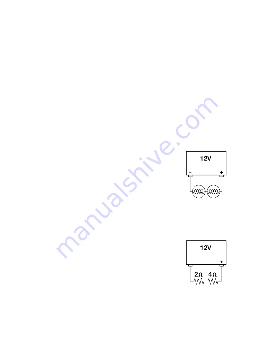
Series Circuits
In series circuits, each electrical device is connected to
other electrical devices in such a way that there is only one
path for the current to follow as it flows from the battery,
through the circuit and back to the battery.
W3000492
Typical Series Circuit
Ohm’s Law in Series Circuits
In a series circuit, the total circuit resistance is the sum
of all the resistors in a circuit. In the example below, the
values of the 2 resistors are added together for the total
circuit resistance.
2
+ 4
= 6
total resistance
Apply Ohm’s Law to find the total circuit current:
I = V
4
R
I = 12 volts
4
6
= 2 amps
Since current is the same at any point in a series circuit, to
find the voltage drop across either resistor, use the above
current value in the formula:
V = I x R
V = 2 amps x 2
= 4 volts
V = 2 amps x 4
= 8 volts
The sum of the voltage drops equals the source voltage:
4 volts + 8 volts = 12 volts
W3000567
11


