background image

9

Mynute 24m

SECTION 4

INSTALLATION

4.1

DELIVERY

Due to the weight of the appliance it may be
necessary for two people to lift and attach the
appliance to its mounting.  The appliance is
contained within a heavy-duty cardboard carton.
Lay the carton on the floor with the writing the
correct way up.

4.2

CONTENTS

Contained within the carton is:

•••••

the boiler

•••••

the wall bracket

•••••

template

•••••

an accessories pack containing appliance serv-
ice connections and washers

•••••

the instruction pack containing the installation &
servicing instructions, user instructions, Bench-
mark logbook, guarantee registration card and a
3-amp fuse.

4.3

UNPACKING

At the top of the carton pull both sides open - do
not use a knife - unfold the rest of the carton from
around the appliance, carefully remove all protec-
tive packaging from the appliance and lay the
accessories etc. to one side. Protective gloves
should be used to lift the appliance, the appliance
back-frame should be used for lifting points.

4.4

PREPARATION FOR MOUNTING THE APPLI-
ANCE

The appliance should be mounted on a smooth,
vertical, non-combustible surface, which must be
capable of supporting the full weight of the appli-
ance. Care should be exercised when determining
the position of the appliance with respect to hidden
obstructions such as pipes, cables, etc.
When the position of the appliance has been
decided - using the template supplied - carefully
mark the position of the wall-bracket (fig. 6) and
flue-hole (if applicable).

4.5

FITTING THE FLUE

The top flue outlet permits both horizontal and
vertical flue applications to be considered, alterna-
tively, the Vokera twin flue system can be utilised
if longer flue runs are required.

4.5.1

CONCENTRIC HORIZONTAL FLUE

(For concentric vertical flue, see 4.5.2).
(For twin flue applications, see 4.5.3).
This appliance can only be used with the standard
60/100mm Uni-flue concentric flue system or the
Vokera parallel (twin) system.

NOTE

These instructions relate 

only 

to the standard 60/

100mm concentric flue system. The appliance flue
outlet elbow can be rotated through 360° on its
vertical axis. In addition the flue may be extended
from the outlet elbow in the horizontal plane (see
2.9). A reduction must also be made to the
maximum length (see table) when additional bends
are used.

Using the template provided, mark and drill a
105mm hole for the passage of the flue pipe. The
hole should have a 1º drop from the boiler to out-
side, to eliminate the possibility of rainwater en-
tering the appliance via the flue.

The fixing holes for the wall-mounting bracket
should now be drilled and plugged, an appropriate
type and quantity of fixing should be used to
ensure that the bracket is mounted securely.
Once the bracket has been secured to the wall,
mount the appliance onto the bracket.

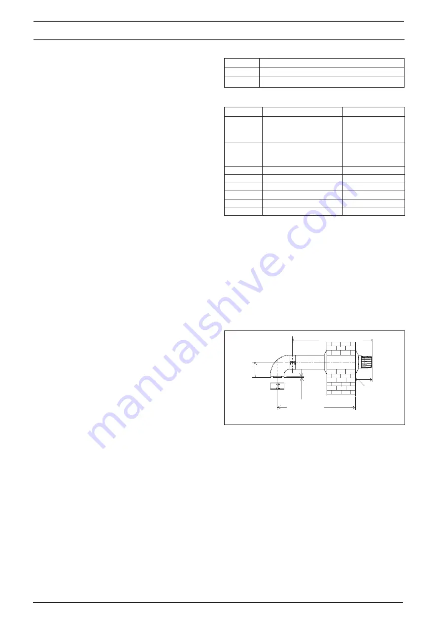
4.5.1.1 FITTING THE HORIZONTAL FLUE KIT (see

4.5.1)

Carefully measure the distance from the centre
of the appliance flue outlet to the face of the out-
side wall (dimension “

X

” see fig. 7).  Ensure the

inner (60mm) pipe is fully inserted into the outer
(100mm) pipe (when the inner pipe is fully inserted,
it stands proud of the outer pipe by 7.5mm). Add
32mm to dimension “

X

” to give the overall flue

length (dimension “

Y

”).

NOTE

The standard horizontal flue kit (part no. 2359029)
is suitable for a distance (dimension “

Y

”) of up to

865mm.
The telescopic flue kit (part no. 2359119) is suit-
able for a distance (dimension “

Y

”) of up to 600mm.

Dimension “

Y

” is measured from the end of the

terminal to the end of the outer (100mm) pipe.

Part No.

Description

Min-Max Length

2359029

Standardl flue kit
For use with add. bends

833 mm

and extensions

(dimension ‘

X

’)

2359119

Telescopic flue kit.
For use with add. bends
and extensions

2359069

750 mm extension

750 mm

2359079

1500  mm extension

1500 mm

2359089

Telescopic extention

350-490 mm

2359049

45º bend (pair)

N/A

2359059

90º bend

N/A

0225760

Wall bracket (5)

N/A

Horizontal flue terminals and accessories

Bend

Reduction in maximum flue length for each bend

45º bend

0.5 metre

90º bend

0.85 metre

Reduction for additional bends

Fig. 7

Dimension “

Y

Dimension “

X

135 mm

7,5

110

Summary of Contents for Mynute

Page 1: ...Mynute 24m Installation Servicing Instructions THESEINSTRUCTIONS TO BE RETAINED BY USER...

Page 2: ...rical connections 13 Commissioning Page 5 1 Gas supply installation 15 5 2 The heating system 15 5 3 Initial filling of the system 15 5 4 Initial flushing of the system 15 5 5 Pre operation checks 15...

Page 3: ...ler which by design incorporates electronic ignition circulating pump expansion vessel safety valve pressure gauge and automatic by pass It is produced as a room sealed category II2H3 appliance suitab...

Page 4: ...tes Thereafter the boiler s output will either be increase to maximum or modulate to suit the setrequirement Whentheappliancereachesthedesiredtempera ture the burner will shut down and the boiler will...

Page 5: ...s Pre charge pressure 1 0 bar 2 4 Dimensions Height 740 mm Width 400 mm Depth 332 mm Dry weight 31 kg 2 5 Clearances Left side 12 mm Right side 12 mm Top 150 mm from casing or 25 mm above flue elbow w...

Page 6: ...Belowgutter drain pipe etc 75mm E Beloweaves 200mm F Below balcony car port roof etc 200mm G To the side of a soil drain pipe etc 150mm H Frominternal externalcornerorboundary 300mm I Aboveground roo...

Page 7: ...suit Details of essential features of compartment cup board design including airing cupboard installations are given in BS 6798 This appliance is not suitable for external installation BS5440 PART 1 F...

Page 8: ...ly this is sufficient however if the system has an unusually high water content it may be necessary to provide additional expansion capacity see 6 19 3 6 6 LOW PRESSURE SEALED SYSTEM An alternative me...

Page 9: ...The gas meter as supplied by the gas supplier must be checked to ensure that it is of adequate sizetodealwiththemaximumratedinputofallthe appliances that it serves Installation pipes must be fitted i...

Page 10: ...rgeneralguid ance only This appliance is a room sealed fan flued boiler consequently it does not require a permanent air vent for combustion air supply When installed in a cupboard or compartment vent...

Page 11: ...e only to the standard 60 100mm concentric flue system The appliance flue outlet elbow can be rotated through 360 on its vertical axis In addition the flue may be extended from the outlet elbow in the...

Page 12: ...irednumberofflueextensionsor bends uptothemaximumequivalentfluelength to the flue terminal using the clips screws and gaskets supplied fig 8 8A The interior trim should be fitted at this point Fig 8 B...

Page 13: ...given to the fact that there is the possibility of a small amountofcondensatedrippingfromtheterminal ensure that the entire flue system is adequately supported use at least one bracket for each extens...

Page 14: ...must always be level with or below that of the exhaust pipe Dependingonsiteconditionsitmaybepreferable to install the terminal assembly prior to fitting the twinfluepipes Markanddrilla130mmholeforthe...

Page 15: ...andreturnconnections connect a 22 mm pipe to the inlet of each valve and tighten both nuts 4 6 3 SAFETY VALVE fig 6 Connect the safety valve discharge pipe to the safetyvalveoutletandtighten Thedischa...

Page 16: ...ablethroughthecableanchorage fig 6 Connectthesupplycablewires earth live and neutral to their corresponding terminals on the terminal strip Ensure that the EARTH wire is left slightly longer that the...

Page 17: ...GHTING Ensure the electrical supply to the appliance is switchedon Switchthetimeclockorprogrammer iffitted toan on positionandensureallexternal controls are also calling for heat SECTION 5 COMMISSIONI...

Page 18: ...nty 5 13 INSTRUCTINGTHEUSER Hand over all documentation supplied with this appliance including these instructions and explain the importance of keeping them in a safe place Explain to the user how to...

Page 19: ...condition of the entire flue assembly Compare the results with the appliance design specification Any deterioration in performance must be identified and rectified without delay Ensurebothflueventuris...

Page 20: ...e electrical supply and attach a suitable manometer to the gas valve outlet test nipple Remove the compensator tube 7 3 1 SETTING THE MAXIMUM BURNER PRES SURE Light the boiler as described in 5 6 and...

Page 21: ...omponents may also assist in locating the fault 7 7 3 POLARITYCHECK With the appliance connected to the electrical supply and using a suitable multimeter carry out the following voltage tests connect...

Page 22: ...LS CN8 3 CN8 5 ON PCB NO NO YES MADE A LINK BETWEEN BLACK BLACK WIRES AT BOILER TERMINAL STRIP SWITCH ON BOILER AND SELECT MODE TO WINTER C H THERMOSTAT AT MAX YES LOOSE THE PUMP ACTING WITH A SCREWDR...

Page 23: ...HECK SUPPLY FUSE CONNECTORS TO BOILER TERMINALS MAINS BLUE BROWN WIRES AT BOILER STRIP NO REPLACE WIRING OR CONNECTIONS TERMINAL STRIP AND CONTROL BOARD YES YELLOW LED BLINKS CHIMNEY SWEEPER CYCLE RES...

Page 24: ...BETWEEN TERMINALS CN8 7 CN8 8 ON PCB NO YES NO CHECK WIRING AND CONNECTIONS NO DO THE AIR FLOW SWTCH TURN ON CHECK WIRING AND CONNECTIONS AIR FLOW SWITCH AND CONTROL BOARD YES NO ARE THE VENTURI TUBE...

Page 25: ...AND SELECT MODE TO WINTER C H THERMOSTAT AT MAX START RESTART THE TEST NO NO YES REPLACE WIRE AND CONNECTIONS REPLACE CONTROL BOARD REPLACE MODULATOR COIL IS THE RESISTENCE OF MODULATOR COIL ABOUT 70...

Page 26: ...R FLOW TEMPERATURE 80 C WAIT WATER FLOW TEMPERATURE 80 C NO YES REPLACE CONTROL BOARD REMOVE JUMPER IS TIMER JUMPER ON RESTART THE TEST DO BURNER AND FAN SWITCH ON OPEN THE LINK BETWEEN BLACK BLACK WI...

Page 27: ...ressure switch T L High limit thermostat P A Water pressure switch S R Primary NTC sensor JP1 Jumper CH only JP2 Setting timer JP3 Natural gas or LPG selector JP4 Jumper disable enable DHW absolut the...

Page 28: ...EGRALTIME CLOCK TheVokera integral time clock Part no 433 should be installed as shown in diagram 19B If a room thermostat is to be connected it should be of the voltage free type and must be con nect...

Page 29: ...Ignition module 10022174 20 Printed Circuit Board 10025340 21 Led Light Guide 10023816 26 Instrumental panel 10027015 27 Knob 10023818 28 Knob 10023817 31 Case 10023822 40 Door panel 10023810 61 Cover...

Page 30: ...lve 2907 23 Connection 10022499 27 Heating cock 1789 31 Venting plugs kit 01005137 63 Pipe 10020898 288 O ring 6898 289 Clip 2223 290 Clip 2165 300 Clip 2222 303 Connection 2217 353 Ogive 1824 400 Wir...

Page 31: ...e 10023603 3 Pump 10024573 7 Pipe 10022000 8 Heat exchanger 10023651 9 Pipe 10022002 12 Washer 2226 201 Washer 5026 285 NTC sensor 8484 289 Clip 2223 290 Clip 2165 299 Washer 10022726 417 Limit thermo...

Page 32: ...or manifold 10025271 4 Burner 10025270 5 Spark electrode 10025985 12 Pipe 10023996 13 Gas valve 10025074 14 Gas valve solenoid 10020838 15 Gas cock 10020897 16 Cover assembly 10024779 18 Glass 1002155...

Page 33: ...Lateral insulating panel 2231 4 Front insulating panel 2232 10 Fan 10020793 12 Connection 10021972 20 Fumes testing connection pipe 10021973 25 Pressure differential switch kit 01005272 28 Stop clip 1...

Page 34: ...e Thiswillensurethattheoutputoftheboiler burner pressure is not compromised due to a high flow temperature 10 5 2 SETTINGTHE MINIMUM BURNER PRESSURE Once the maximum burner pressure has been checked a...

Page 35: ...33 Mynute 24m...

Page 36: ...0 333 0520 Fax 01442 281403 After Sales Service Tel 0870 333 0220 Vok ra Ireland West Court Callan Co Kilkenny Tel 05677 55057 Fax 05677 55060 Vok ra Ltd reserve the right to change the specifications...

Reviews: