background image


© 2020 Virginia Diodes, Inc.

—All Rights Reserved 

7 October 2020 


WR10 1-Inch, Self-Symmetric Taper


PM5B Mechanical Drawing: WR10 1-Inch Taper


Summary of Contents for Erickson PM5B

Page 1: ...979 Second Street SE Suite 309 Charlottesville VA 22902 6172 USA Tel 434 297 3257 Fax 434 297 3258 www vadiodes com 2020 Virginia Diodes Inc All Rights Reserved PM5B Operational Manual 2020 ...

Page 2: ...e 10 Section 7 PM5B Software Guide USB and GUI Pages 11 13 Introduction and Software Startup Page 11 GUI Control Buttons and Overview Page 12 GUI Control Buttons Detailed Functions Page 13 Appendix 1 Programming Commands Communications Pages 14 18 Programming Communications and Commands to the PM5B Page 14 Communications and Protocols from the PM5B Page 15 Status Byte 1 Status Byte 2 Status Byte 3...

Page 3: ...n in this PM5B product manual before turning on or using your power meter Start Up Operation procedures must be followed for proper function of the PM5B If you have questions contact VDI at 434 297 3257 before using your power meter 1 Use of any attachments not authorized by VDI may void the PM5B s limited warranty and could pose a hazard to the operator Check with VDI before any measurement conne...

Page 4: ...switch DC Power Input 9V 4A Calibration Input Banana jacks for DC calibration max 15V USB Interface Type B jack Analog Output via BNC to other equipment 10 to 10 VDC Front Panel Rear Panel Sensor Head Overview Section Two Sensor Head with a 1 inch WR10 straight waveguide and a 1 inch waveguide taper to WR10 are attached Copper Flange is nickel plated tapped holes are easily stripped Keep waveguide...

Page 5: ...output or analog output The switch reads in log dB units with 0 corresponding to no correction Positive values correspond to correcting for input loss and negative values correspond to correcting for input gain The maximum correction is 29 9 dB The correction for the internal waveguide loss is only about 0 2 dB at 100 GHz See Section 5 for details about using tapers and horn antennas See Appendix ...

Page 6: ...n input power Operational temperature range 10 30 C Required power 100 240 V 50 60 Hz Maximum Power In CW operation do not exceed 200mW In pulsed operation the PM5B measures the average power from pulsed signals that have pulse rates faster than 5 Hz depending upon the scale used The average signal power must be kept below 200mW for safe operation or the sensor head may be damaged The peak power i...

Page 7: ...nual concerning Use of Tapers in High Frequency Measurements located in Section 5 11 Review conditions affecting Power Meter Response Times located in Section 6 12 See additional information detailing PM5B software the USB and GUI located in Section 7 Modes of Operation Range Switch Selections Fixed Range Mode Fixed Range Mode can be entered by setting the Range Switch to 200 μW 2 mW 20 mW or 200 ...

Page 8: ...ull equilibrium takes over one hour to achieve under such conditions Significant drift and zero offset can be induced by physically rotating the sensor head A noticeable source of apparent drift is due to the wideband response of the sensor The sensor response band extends from 60 GHz to at least the visible spectrum and so it responds to thermal emission from any object Viewing an object only a f...

Page 9: ...n the expected beam size and a precise beam match is not needed since the waveguide can carry several modes DO NOT use a horn tapering down to single mode size and then a taper up to WR10 since this adds greatly to the waveguide loss and makes mode matching much more critical Flange Details The UG387 waveguide Flange is nickel plated copper and its tapped holes can be stripped very easily compared...

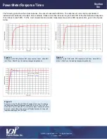
Page 10: ...res below Figure 3 Response on the 200 µW scale 90 response is at 12 sec while 99 is at 31 sec After 60 sec the reading changes insignificantly Figure 4 Response on the 2 mW scale 90 response is at 0 6 sec while 99 is at 5 sec After 8 sec the reading changes insignificantly Figure 5 Response on the 20 mW and 200 mW scales After 3 sec the reading changes insignificantly Response settled to 99 is at...

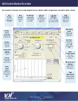
Page 11: ...y be automatically loaded 5 Run PM5B exe installed during setup in the installation directory Doing so will open the window shown in Figure 6 6 Enter the serial number found on the sensor head in the SN field Default is 235V 7 Run the program by clicking on the arrow in the top left corner 8 Clicking the Run Continuously button from ON to OFF will stop the program Figure 6 Screen shot of PM5B exe ...

Page 12: ... name a file for logging power measurements Start Logging starts or stops logging data to a selected file Start Strip Chart starts or stops plotting to the graph below Get Rev populates the Version field with the PM5B firmware revision number Run Continuously starts stops continuous data collection Measurement Interval sets time Sec between points in strip chart plot High Resolution switches comma...

Page 13: ... faster than the sampling rate of the PM5B as described in the specifications High Resolution switches the program to a different command set that returns more bits when measuring power The default command set returns 16 bits for the power measurement over the USB same rate as PM4 However the PM5B has up to 10 times less noise Sixteen bits does not provide enough resolution to realize the full ben...

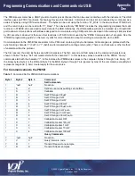
Page 14: ...x21 or 0x3f and terminated with a carriage return x0d There is no checksum or other method of validation within the protocol The first second third and last bytes are ASCII characters The first second and third bytes are the command characters as shown in Table 1 below Set commands start with the character In this instance values are written to the PM5B Query commands start with the character In t...

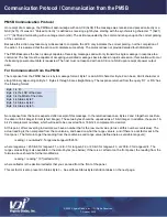
Page 15: ...turned from the query D1 or DS has the following format Byte 1 is D Byte 2 is the LSB of the data Byte 3 is the MSB of the data Byte 4 is Status Byte 1 Byte 5 is Status Byte 2 Byte 6 is Status Byte 3 No response from the host is expected after receipt of this message In the returned response Bytes 2 and 3 together constitute the data in 16 bit integer format short integer These two bytes should be...

Page 16: ...bit 0 Local Remote 1 Remote 0 Local Status Byte 2 Definition bit 7 4 Cal Factor ones digit binary encoded bit 3 0 Cal Factor decimal point digit binary encoded Status Byte 3 Definition bit 7 5 Range Status Bits Range Selected Auto determined by Byte1 bit7 000 OFF no range selected 001 200 µW 010 2 mW 011 20 mW 100 200 mW 111 Error multiple ranges selected bit 4 Cal Factor Sign digit 1 is 0 is bit ...

Page 17: ...is set to Remote this will change the range to 2 mW Bytes 4 7 must be sent but the receiver ignores R3 if the front panel rotary switch is set to Remote this will change the range to 20 mW Bytes 4 7 must be sent but the receiver ignores R4 if the front panel rotary switch is set to Remote this will change the range to 200mW Bytes 4 7 must be sent but the receiver ignores R5 if the front panel rota...

Page 18: ...until the PM5B gets a D1 command or until the power is turned off The internal sample rate is 1 Hz on 200 W range 5 Hz on 2 mW range 20 Hz on 20 mW range and 35 Hz on 200 mW range VC will request the firmware code and secondary firmware code revision data Bytes 4 through 7 must be sent but the receiver ignores High Resolution Get Power Command The PM4 command structure returns 16 bits representing...

Page 19: ...rm such measurements Possible methods to compare power measurements made by different research laboratories are also important topics but they have not been considered here VDI will update this document from time to time to reflect improved measurement techniques and equipment upgrades Figure 7 Data for taper and PM5B sensor head loss for various frequency bands are shown The loss through the PM5B...

Page 20: ...PM5B s Sensor Head weighs approximately 8 ounces about 22 kg Despite its robust construction it should not be dropped or roughly handled since its internal components connection points and the Flange can be misaligned or damaged Appendix Three PM5B Mechanical Drawing Sensor Head ...

Page 21: ... 2020 Virginia Diodes Inc All Rights Reserved 7 October 2020 WR10 1 Inch Self Symmetric Taper PM5B Mechanical Drawing WR10 1 Inch Taper ...

Page 22: ...bove 100 GHz The Virginia Diodes staff of engineering and physical science professionals works to continually improve our products We also depend upon feedback from colleagues and customers Ideas to simplify the meter s operations improve performance or add capabilities are always welcome Be certain that Virginia Diodes has your latest contact details including a phone number and an email address ...

Reviews: