© 2020 Virginia Diodes, Inc.
—All Rights Reserved
7 October 2020
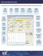
Each button in the top row of the Graphical User Interface (GUI) implements a function when clicked
•
“Get Power” returns the measured power from the PM5B.
•
“Zero” is equivalent to the front panel “Zero Button” on the instrument.
•
“Set Range” changes the range to the value selected by the “Range” knob below the serial number field.
•
“Range Hold” applies and also holds the range setting selected by the “Range” knob.
•
“Set Cal Heater” sets the calibration heater according to the value selected by the “Calibration Heater” knob to the right of
the
“Range” knob.
•
“Log File Settings” opens a window that allows browsing file names/locations in which to place logged readings. It also
allows creating an original filename and location for logging power measurements to a text file.
•
“Start Logging” starts and stops logging data to a selected file.
•
“Start Strip Chart” starts and stops plotting to the graph at the bottom of the program’s window.
•
“Get Rev.” returns the revision number of the PM5B firmware and places this number in the “Version” field.
Other GUI Controls and Indicators
•
“Measurement Interval” sets the time in seconds between points for plotting to the Strip Chart and logging to a file. The
program will attempt to achieve this time, but will not be able to go faster than the sampling rate of the PM5B as described
in the specifications.
•
“High Resolution” switches the program to a different command set that returns more bits when measuring power. The
default command set returns 16 bits for the power measurement over the USB (same rate as PM4). However, the PM5B
has up to 10 times less noise. Sixteen bits does not provide enough resolution to realize the full benefits of the noise
improvements of the PM5B; therefore, the PM5B also responds to a new command for measuring power that returns
more bits. The PM5B does not return the status byte while returning a power measurement with higher resolution. When
“High Resolution” is "ON" the calibration factor used for the GUI outputs will not be updated until “High Resolution” is
turned
“OFF.”
•
“Status” shows the settings of all meter functions. The settings of the switches determine which functions are enabled.
•
“Remote/Local” shows the front panel range switch setting. “Local” refers to any range other than “Remote.” In “Local” the
GUI cannot set the range, but will perform the other functions.
Any selection of the back panel calibration heater switch other than
“OFF” allows full control of the calibration heater. For
example: Even on the 200 µW setting, the meter can be calibrated on any range.
•
“Cal Heater Switch State” shows the position of the rear panel switch.
•
“Cal Heater Status” shows the actual calibration setting.
The last row of the GUI
shows the setting of the “Cal Factor” front panel switch.
GUI Control Button Details


