


VIP Vision Intercom Installation Manual - Version: INT-Q320
24
4.1 Manual Configuration of 1 Residential Door Station and 1 Monitor (Cont.)
13. Press and hold down the
Settings button
- after 6 seconds, a prompt will appear. Enter your
password
(888888),
then select
OK
. (Fig 4.5)
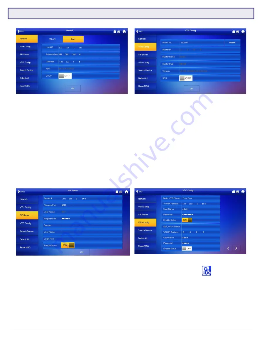
14. Select
Network
and set the
IP Address, Subnet Mask and Gateway
to suit your network, or, if no remote
connection is required, use the example in the table above. (Fig 4.6)
15. Select
VTH Config
and set the
Room No.
to 9901#0. Ensure
Master
is selected. Select
OK
. (Fig 4.7)
16. Select
SIP Server
and set the
Server IP, User Name and Login Pwd
. These will be the IP Address, username and
password of the Door Station (192.168.1.108, admin, admin123). Do not modify the register password (123456 by
default). Select
OK
. (Fig 4.8)
17. Select
VTO Config
. Set the
Main_VTO Name
to an easily identified name for the door (e.g Gate or Doorbell).
Set the
VTO IP Address, User Name and Password
. These will be the IP Address, Username and Password of
the Door Station (192.168.1.108, admin, admin123).
Turn the Enable Status button OFF then ON
to save the
settings.
Ensure it is left in the ON position.
(Fig 4.9)
18.
Allow up to 10 minutes for the Indoor Monitor to connect to the Door Station.
Once the “
” icon disappears,
you can press the call button on the Door Station to test the connection.
Fig 4.9:
VTO Config
Fig 4.6:
Network Settings
Fig 4.7:
VTH Config
Fig 4.8:
SIP Server Config