


VIP Vision Intercom Installation Manual - Version: INT-Q320
20
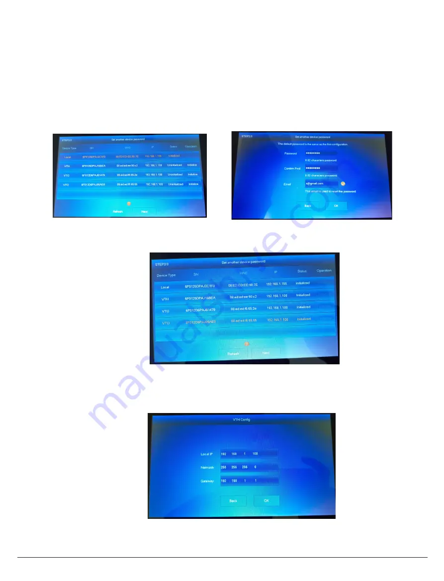
5. If prompted with
Do you want to do quick configuration?
, Select
OK
. If Step 3 was completed, skip this step.
(Fig 3.11)
6. Select
Initialize
next to the
second uninitialized Indoor Monitor (VTH)
and set a
password
(888888) and
.
Select
OK
.
7. Select
Initialize
next to the
first uninitialized Door Station (VTO)
and set a user
password
(admin123) and
.
Select
OK
.
8. Select
Initialize
next to the
second uninitialized Door Station (VTO)
and set a user
password
(admin123) and
. Select
OK
. (Fig 3.12)
9. Once all of the devices are initialized, select
Next
. (Fig 3.13)
10. Select
Edit
next to the
first
Indoor Monitor (VTH)
. Set the device type to
Main
and set the
IP Address
(192.168.1.112),
Netmask
(255.255.255.0) and
Gateway
(192.168.1.1). Select
OK
. (Fig 3.14)
Fig 3.11:
Device Initialisation
Fig 3.12:
VTO Initialisation
Fig 3.13:
Device Initialisation
Fig 3.14:
VTH Config