background image


57 


3.


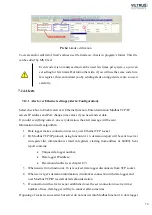
And  mostly  important  is,  that  total  number  (sum)  of  interfaces  and  meters,  per 

d

ata 

logger can be 5 devices. So, if to one interface you connect 4 meters, you can use 1 more 

interface, but to this interface you can connect only 1 meter, because 4+1 is 5 (MAX 

number) – you can’t connect one more meter to any interface! 

To 

CONFIGURATE 

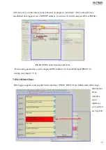
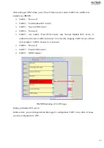
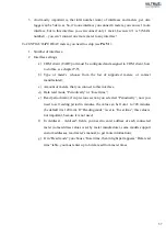
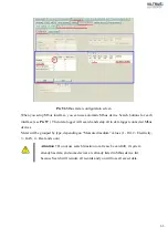
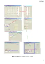
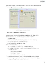
HEAT meters, you need to setup (see 

Pic 51 

): 


1.


Number of interfaces; 

2.


Interface settings: 

a)


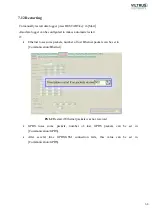
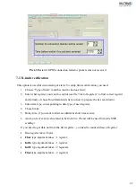
COM client (UART port must be configured and assigned to COM client, how 

to do this, see chapter 

7.7

); 

b)


Type  of  meter’s  (choose  from  the  list  of  supported  meters,  or  contact 

manufacturer); 

c)


Amount of meters, that you connect to this interface; 

d)


Data read mode, “Periodically” or “In set time”; 

e)


Read period (min), if in previous section you selected “Periodically”, now you 

need to set reading period in minutes, the value can be from 1 to 720 minutes 

(be default it is 120 min). If “Reading mode” is set to “In set time”, this value is 

not important, because it is not used; 

f)


In  Address1  ..  Address5  fields,  you  need  to  enter  address  of  each  connected 

meter (some address values is set by meter manufacturer, some models support 

custom addresses, read meter’s manual, to get more information); 

g)


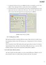
If in “Read mode” you choose “In set time, then in right part appears “Data read 

time” table, you must enter up to 6 data read from meter times. 

Summary of Contents for MX-7

Page 1: ...2 ...

Page 2: ...3 3 5 Indication 13 3 6 Power supply 14 3 7 Construction 14 3 8 Working conditions 14 3 9 Safety parameters 14 3 10 Other parameters 14 4 SUPPORTED FUNCTIONS 15 4 1 Connection and communication functions 15 4 2 Measuring functions 17 4 3 Archive functions 18 4 4 Alarm functions 19 4 5 Meters and data collecting functions 19 4 6 Time functions 19 4 7 Other functions 20 5 INSTALLATION 21 5 2 Connect...

Page 3: ...ected devices 56 7 11 External modules Communication External module RAY 1 64 7 12 Restarting 68 7 13 Limits verification 69 7 14 Alerts 70 7 15 Data storing to archive Archives 74 8 STORED DATA 77 8 1 Loging analog input channels Archives Values Analog inputs 77 8 2 Heat counter data Archives Values Heat 78 8 3 GAS meter data Archives Values GAS 78 8 4 Logging water data Archives Values Water 79 ...

Page 4: ...5 9 6 USB cable 85 9 7 Installing VILTRUS USB driver 85 9 8 TCP IP settings 87 ...

Page 5: ...tandard defines the electrical characteristics and timing of signals the meaning of signals and the physical size and pin out of connectors RS232 interfaces are prepared for connection of peripheral devices example energy meters data loggers machines and etc TD contact for transfer data wire of RS232 socket RD contact for read data wire of RS232 socket DTR contact for Data Transmit Ready wire of R...

Page 6: ...equest wire Current loop are used where a device must be monitored or controlled remotely over a pair of conductors Only one current level can be present at any time CL contact for current loop positive wire CL contact for current loop negative wire 1 2 LED indications Status device status indicating LED Output status of power for external device indicating LED TX RX data transfer receive indicati...

Page 7: ...is a unique identifier assigned to most network adapters UART An Universal Asynchronous Receiver Transmitter is a type of asynchronous receiver transmitter a part of computer hardware that translates data between parallel a serial forms UART are commonly used in conjunction with communication standards such as EIA RS 232 RS 422 or RS 485 ...

Page 8: ...s Directive or RoHS 2 2 Safety instructions To install and setup device special technical knowledges are needed Call to seller or certified professionals to connect and setup device Before connecting to power supply be sure that 1 Data logger is not damaged no cracks melted broken or exposed areas 2 Data logger is used with right and correct thickness cables 3 Data logger and antenna are installed...

Page 9: ...hable place with markings Don t use 1 Device under open water in rain and if water is splashing on data logger or connected devices 2 Device if enclosure connected cables or other connected devices are damaged 3 External Back Up batteries for powering data logger Use device by manufacturer s regulations otherwise you can damage data logger or other devices In that case manufacturer s warranty coul...

Page 10: ...analog current signal values Follow status of objects Form control signals Store accounting and measurement data Carry out initial processing of data Generate reports to service personnel at the limit of deviation from the preset parameters and status discrete signals change Send all data through GSM GPRS and Ethernet Pic 1 Data logger s flowchart ...

Page 11: ...bout data logger and if you will need any consultations from technical center or manufacturer please let them know full Manufacturer s code and Serial No Configuration code provides full information about installed interfaces supported power and other technical information ...

Page 12: ...S Open contact up to 50V up to 500mA Analog INPUTS 0 4 20mA 0 5 mA 250Ω error 0 15 3 4 Protection Insulation voltage between power supplier and second circuits 1500 V Insulated interfaces B C D see Configuration code Analog INPUTS Yes insulation voltage 500V Discrete INPUTS Yes Non insulated from discrete outputs Discrete OUTPUTS Yes Non insulated from discrete inputs 3 5 Indication Indication typ...

Page 13: ...et requirements LST EN 61010 1 2002 Electromagnetic compatibility Meets requirements of LST EN 55022 2000 A1 AC 2002 A2 2003 LST EN 55024 2000 A1 2003 A2 2003 LST EN 61000 4 2 A1 A2 2002 LST EN 61000 4 3 A1 2004 LST EN 61000 4 4 2005 LST EN 61000 4 5 2002 A1 2003 LST EN 61000 4 6 2002 A1 2003 3 10 Other parameters Archive storage memory 1 8 MB default 2 MB Configuration settings storage without po...

Page 14: ...ected to intranet over GPRS or Ethernet Serial interfaces Modbus RTU server Modbus RTU connection server is used to establish local Modbus RTU client This function enables data logger to get data from other devices connected to data logger locally in Modbus RTU protocol GPRS Ethernet Modbus TCP IP server Modbus TCP IP server is used to establish remote connection with data logger Modbus TCP IP cli...

Page 15: ...query to next Server and so on Query contains TCP port MAC address every data logger has unique MAC data logger s IP address Then query is sent over Ethernet Remote Server over Ethernet returns answer to data logger s Modbus Server Pic 2 Scheme how data logger sends data in Modbus Server mode 4 1 3 Modbus Client The query received over Ethernet in to Data logger s Modbus TCP Server which contains ...

Page 16: ...mit deviation event fixed For more information about events and alarms see chapter 4 4 Discrete inputs Discrete IN purpose Can be used for discrete IN state follow either as impulse meter or alarm signal Current state Data logger periodically tracks all discrete inputs status and during change on each channel it stores current state change with real time value Impulse meter Each discrete channel c...

Page 17: ... water meter parameters with real time stamp Electricity accounting Electricity accounting archive consist records of current electricity meter parameters with real time stamp Impulse Impulse meter archive consists of discrete channel s number total impulse count and real time stamp Discrete IN OUT Discrete IN OUT archive consists of discrete channel s number discrete channel s state and real time...

Page 18: ...erman III Multical 601 Elkora FP 93 Supertrol II If some meters are not supported additional protocols can be implemented Gas accounting Data logger can read data from gas meters Unigas Roots PTZ TC 90 Uniflo If some meters are not supported additional protocols can be implemented M bus meters water electricity M bus meters can be connected directly to Mbus or through Mbus RS232 converter Data log...

Page 19: ...rm it s reachability Data reading Modbus register field formation User has possibility to form Modbus register field manually In defined registers data can be read only from formed Modbus register block Limits verification Modbus register check Data logger has possibility to check limits for any register it can be analog value meters data time records archives and etc Alarm limits Data format char...

Page 20: ... TX and reception RX switch them that TX from one device has go to RX from another and RX to TX If you connect TX to TX and RX to RX data will not be sent and received through these interfaces First turn ON the power on peripherical devices and only when they boots up turn ON data logger s power 5 3 Switching Devices has special interfaces which using jumpers can be switched between few prepared i...

Page 21: ...ocket X12 Pic 5 Jumper positions for Universal interfaces 5 3 2 Power for external devices U Corrector maximal supported current is 20 mA Power for external device connection use UART2 socket X13 one wire connect to GND and other to U correct Device can supply 3 6 5 6 8 10 voltage Set DIP switch into correct positions to set voltage that you need RS485 RS232 Data Req Mbus RS485 RS232 Mbus ...

Page 22: ...23 see Pic 6 3 6 V 5 V 6V 8 V 10 V Pic 6 Power for external device DIP switch ...

Page 23: ...ed requests and notifications If you need to restart data logger Necessary restart with RED light appears this means you have made some major changes and to take action data logger needs to be restarted restart by pushing Restart button on Start tab see Pic 7 Pic 7 Common information Start Program is prepared for slow speed GPRS connection For that purpose you can Get and Set data of specific grou...

Page 24: ...ck box Get all at connection or use Get all button to read all data see Pic 9 Pic 9 Preparing for high speed connection 6 2 Before connecting To communicate with data logger you need to prepare cables and correctly setup your computer Be sure your computer stands at least minimal requirements ...

Page 25: ...over RS232 you need to choose correct RS232 cable configure serial port and find number of serial port that is connected to data logger s serial com port To establish connection you need In Start Connection parameters choose Modbus RTU connection type Select Com port that you will use for connection with PC If connection fails recheck cabling and COM port see Pic 11 Pic 11 Connecting over COM port...

Page 26: ...LTRUS USB driver installation guide about how to install driver Connecting to data logger through USB virtual COM port you need to choose Modbus RTU connection type Select Com port that you will use for connection with PC If connection fails recheck cabling and COM port see Pic 12 Pic 12 Connecting over USB 6 5 Connecting over Ethernet and GSM Start To connect with data logger over Ethernet if Eth...

Page 27: ...is is system standard Modbus TCP IP port change it if you need If you have slow connection for example you are using GPRS connection or etc set timeout time in msec range from 400 to 20 000 recommended 3 000 ms By pressing Connect you will be connected to data logger If connection fails recheck cables communication type IP address and try to connect again see Pic 13 Pic 13 Connecting over Ethernet...

Page 28: ...ps of settings Clock synchronization yellow zone see Pic 14 Summer winter time day light saving blue zone see Pic 14 Set current PC time green zone see Pic 14 Pic 14 Groups of time parameters Time parameters 7 1 1 Set PC time To synchronize PC and data logger press Set PC time button see Pic 15 Pic 15 Synchronize data logger with PC time ...

Page 29: ...onization from GSM provider every time when data logger connects to GSM network NTP Server you can add IP of local SNTP server or use public Synchronization will be made in set periods of time Pic 17 NTP time synchronization algorithm Synchroniz e time Yes Answer received Yes No No Sending request Setting accurate time Accurate time Time of NTP server answer receive time request send time 2 Beginn...

Page 30: ...October If you neet to change time on other month use option By month in that case time will be changed at 3 00AM of the last Sunday of your set months If you will set months 3 and 10 system time changes coincide with time changes in Mach October option see Pic 19 Pic 19 Day light saving time By month Time parameters Data logger also has possibility to change time in specific day option By date In...

Page 31: ...ration Conversion into physical parameter range Min value and Max value Alarm filter time Alarm limits upper and lower Alarm case Out of range Out return to range Data logger periodically analog measurement perod 0 1 seconds measures current of all Analog channels and converts to physical value User can chose from three 0 20mA 4 20mA and 0 5mA with accuracy 0 005mA measurement ranges see Pic 21 Fr...

Page 32: ...tion then current value will be equal to the last 1 5s average value If averaging duration is set to 0 filtration will not be done Pic 21 Setup Analog inputs Current values data logger compares with user defined minimum and maximum signal values In case of deviation from minimum and maximum values that extends user defined Alarm filtering time in seconds see Pic 22 report is initiated about deviat...

Page 33: ...l deviation from minimum and maximum value limits In case of deviation data logger initiates report via Ethernet and or GSM GPRS Events about deviation is fixed by user defined time intervals when signal goes out of range and out return case see Pic 22 Also data logger stores analogical measurement s average values in user defined periodicity 7 2 2 Calibration parameters Performed function Calibra...

Page 34: ...om file or calibrated using methrologicaly tested equipment To calibrate with reference current open screen Analog inputs Calibration connect for the beginning 0 1mA current to first channel on Analog inputs the current value you can see on column ADC Code and press FIX 0 1 mA button see Pic 24 Background of color under the key FIX 0 1 mA will change to green and lower calibration value will be se...

Page 35: ...ters D In channel usage Debounce filtering time Impulse counting mode Impulse multipier just to view multipliered impulse quantity this parameter will not effect to Archive stored value Alarm state None disabled Input open Input closed or in both cases Archive state None disabled Input open Input closed or in both cases Current discrete channel s states are shown by corresponding pictures Open and...

Page 36: ...d in case of changes takes action see Pic 27 Pic 27 Discrete IN channel data flow schema Discrete channels can be used as impulse counters see in Blue color marked group in Pic 26 With enabled impulse mode counted impulses are periodically storred in to Impulse achive with a real time record to setup period see chapter 7 15 Data storing to archive Archives ...

Page 37: ...ust need to view status of Discrete channels select Discrete input mode Like in other modes by enabling archiving you can store changes of discrete channels to archive choose when to save on Open on Close or in Both cases how to manage Events see chapter 7 15 Data storing to archive Archives and to view see chapter 8 6 Discrete inputs log Archives Values Discrete inputs Alarm mode will not work if...

Page 38: ... defined duration control impulse In section Time of impuse set duration value can be from 100 to 20 000 msec see Pic 28 If some parameters was changed press Set to send data to data logger 7 5 USB device USB device interface is not listed in Manufacturer s code but is installed by default This interface is used for local configuration how to connect to data logger using USB device see chapter 6 4...

Page 39: ... To setup connection in Communication Ethernet enter basic data IP address Gateway IP and Subnet mask by pressing Set write data to data logger and Restart data logger see chapter 7 12 Restarting Pic 29 Setup Ethernet interface Communication Ethernet For security reasons IP filter is installed data logger support up to 5 exceptions Enable IP filter and add at least one IP address in list of except...

Page 40: ...g data function enable function enter IP address of the device that you are pinging in and time interval in seconds see Pic 31 Pic 31 Ethernet PING setup Communication Ethernet To avoid hanging data logger can initiate self restart if packets over Ethernet was not received more than set time you can enter any time in seconds from 600 to 3600 see Pic 31 ...

Page 41: ...pany network GPRS devices cannot use dynamic addresses Turned ON data logger is establishing connection if SIM card is inserted this takes about 30s Pic 32 Setup groups of GPRS GSM settings To use GPRS GSM modem you must enable it by checking Enabled box Also you can choose data transfer protocol GPRS GSM GPRS GSM see Pic 33 Pic 33 GPRS GSM setup section Some GPRS providers has additional security...

Page 42: ...field Assigned IP see Pic 34 Pic 34 GPRS connection data and status About routing parameters read in chapter GPRS Ethernet G E and Ethernet GPRS E G routing see chapter 7 9 4 7 8 Serial interfaces Data logger supports most popular Serial interfaces RS485 RS232 Opto MBus and Current loop Information about installed serial interfaces you can find on Top label ...

Page 43: ...s 5 6 7 8 Stop bits 1 1 5 2 Packetization Time in field Packet time you can set packet interval 1 10000 msec Symbol if you use this packetization method you need to write Packet symbol in HEX format Length if you select this packetization method you need to write number of bytes per packet in field Packet byte count 1b time is connecting packetization of methods Length and Time and you need to wri...

Page 44: ...t symbol any Hex number that will mean end of packet Packet byte count Mode Full duplex Half duplex Destination of DTR Always OFF Always ON OFF when sending ON when sending For RS485 interfaces Destination of DTR must be set OFF when sending Pic 35 Setup UART Basic ...

Page 45: ...UART choose which UART Universal Asynchronic Receiver Transmitter port will be accessed by COM values are from UART1 to UART5 and UART7 By default UART6 is used by Modbus RTU Server and is used to configure data logger COM client is used to read data from meter and we need to set up COM client not UART see Pic 37 Pic 37 COM Client setup screen ...

Page 46: ...rst COM Clients and Second Modbus RTU Server is conflictin on the same UART and it mus t to be fixed by changing UART for one of them for example to UART1 because he is not used UART6 Not used UART7 Fourth COM client UART8 GPRS modem Pic 38 Monitoring of UART usage Setting up Modbus RTU server In this section you can change default data logger s configuration UART to any other or choose one more c...

Page 47: ...on you can choose UART for Modbus RTU client Modbus RTU Clients usually are used for connection to other Modbus RTU devices device must support Modbus RTU server mode like valves heat correctors data logger s or etc Pic 40 Modbus RTU Client section Interfaces Virtual interfaces ...

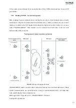
Page 48: ...ange with terminal device when terminal device directly answers one by one FIFO method after the response to previous query or after a specified period of time TimeOUT to a high level system s request is called Routing TCP IP serial request Data transfer can be initiated only from high level system sides At one time data can be send only in one direction request or answer 7 9 1 Routing TCP IP seri...

Page 49: ...e is added to the TCP packet and redirected to high level system and or vice versa is called TRANSPARENT Data transfer can be initiated from both sides And can work bidirectionaly at the same time Pic 42 Schema of transparent mode TRANSPARENT mode is used for direct connection between server and terminal device Thisis useful if terminal device use special protocol to setup or control terminal devi...

Page 50: ...wer to request of one PC will be sent to all to channel connected PC s Even if request was sent from other PC 7 9 3 Modbus TCP IP routing Is used for setting up Modbus TCP IP routing To setup you must to chose routing type only one type can be used Modbus address or TCP port Modbus addresses routing is used for range of addresses routing to Modbus RTU Client This is used to route all data that Mod...

Page 51: ...ht set TCP port Accessing this port you will automatically routed to set Modbus RTU client Modbus TCP IP server is always enabled you can change socket time in seconds Modbus TCP IP is used in External modules connection example see chapter 7 9 4 picture Pic 61 Pic 44 Modbus TCP IP routing by Modbus address range Pic 45 Modbus TCP IP routing by TCP port ...

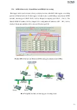
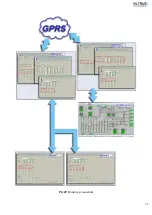
Page 52: ...ter mode is establishing connection to GPRS network incoming port Port1 Port5 will be changed to outgoing port Port1 Port 2 The internal GPRS IP address will be changed in to configurable IP addresses IP1 IP5 will be checked Checksum and data will be sent over Ethernet port 502 Pic 46 GPRS Ethernet and Ethernet GPRS routing Communication GPRS Pic 47 Simplified scheme of data loggers in routing mod...

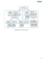
Page 53: ...54 Pic 48 Routing configuration example ...

Page 54: ...55 Pic 49 Routing screenshots ...

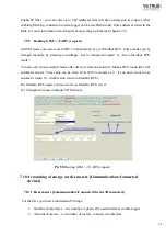
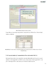
Page 55: ...lso can choose default mode after device restart and return to Mobus RTU mode time for automatic return Time value can be from 10 to 65535 seconds or 0 if you don t want to use automatic return 0 disable auto return to Modbus RTU For Modbus RTU mode you need to chose Modbus RTU server For Transparent mode configure COM clients Pic 50 Routing GSM UART request 7 10 Accounting of energy carrier meter...

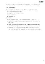
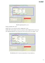
Page 56: ...supported meters or contact manufacturer c Amount of meters that you connect to this interface d Data read mode Periodically or In set time e Read period min if in previous section you selected Periodically now you need to set reading period in minutes the value can be from 1 to 720 minutes be default it is 120 min If Reading mode is set to In set time this value is not important because it is not...

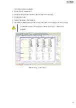
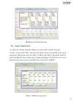
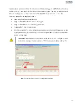
Page 57: ...de you can see field name and by using Drag and Drop you can drag parameters form All available fields table to Data for logging table you need to drag in to right side of table and take care to drag into right row By choosing data in Data for logging table you will unify logged data values and in this case you can compare data from different type of meters Do not forget to write data to data logg...

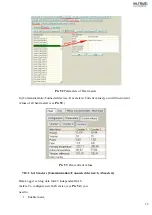
Page 58: ... Current values you will find current values of all heat meters see Pic 53 Pic 53 Heat current values 7 10 2 GAS meters Communication Connected devices GAS meters Data Logger can log data form 5 independent GAS meters To configure new GAS meter see Pic 54 you need to 1 Enable meter ...

Page 59: ...60 2 Set COM port number UART port must be configured and assigned to COM client on ...

Page 60: ...to get more information 6 Multiplier 1 and Multiplier 2 some meters gave values without the decimal point and using Multiplier you can correct value Multiplier 1 is used for Totalizer value Multiplier 2 Flow value Only meters that doesn t use decimal point let you change values in this fields If you can t enter new value this meens multiplication is not needed Pic 54 GAS meters configuration scree...

Page 61: ...32 RS485 to Mbus converter you can extand range of supported devices so total number meters per data logger is 400 see Pic 56 Setting up Mbus interfaces 1 Enable or Disabel interface by using check box 2 Assign COM client by entering number of COM port UART port must be configured and assigned to COM client on how to do this see chapter 7 7 3 See and correct if you need Read period value in minute...

Page 62: ...h and setup all to data logger connected Mbus devices Meter will be grouped by type depending on Measured medium values 1 Oil 2 Electricity 3 GAS 4 Heat and so on Attention Do not use search function or at lease be carefull if system already has data and some devices are already listed in Mbus device list because Search will reindex all records and you will lose all saved data ...

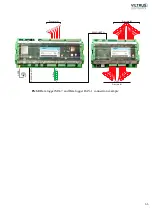
Page 63: ...munication Connected devices Mbus devices Current values Water 7 11 External modules Communication External module RAY 1 Data logger has possibility to be expanded by connecting additional Discrete IN ports over a serial interfaces Todata logger MX 7 over RS485 can be connected up to 32 data loggers RAY 1 And up to 5 data loggers RAY 1 this means up to 160 Discrete Inputs for alarms ...

Page 64: ...bouth devices Setup Modbus RTU client on master data logger Setup Modbus RTU server on Data logger RAY 1 Configure RAY 1 as External mode If to Data logger RAY 1 with configuration program you will connect through Master data logger not directly then additionaly you need to setup Modbus TCP_IP to Modbus RTU address routing range Attention Basic address of VILTRUS made devices is two last digits of...

Page 65: ...66 Discrete IN Discrete IN Discrete IN Pic 60 Data logger MX 7 and Data logger RAY 1 connection example RS485 UART1 D16 M1 M2 M4 M5 D32 D28 GPRS RS485 UART7 MBus ...

Page 66: ...67 Pic 61 Setting up RAY 1 as External module by example ...

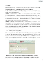
Page 67: ...restart if Ethernet loses some packets number of lost Ethernet packets can be set in Communication Ethernet Pic 62 Restart if Ethernet packets was not received GPRS loses some packets number of lost GPRS packets can be set in Communication GPRS After several time GPRS GSM connection fails this value can be set in Communication GPRS ...

Page 68: ...Main fields list on how to prepare the list read down 3 Enter data type corresponding to data type of used register 4 Chose limits 5 Delay time if you want to filter accidental ar short time events 6 And a code of event value must to be from 0 to 99 and will be used for alerts SMS sending If you need to get data not from the first register you need to count address of register One register takes 2...

Page 69: ...ation the alert message will be sent Information transfer algorithm 1 Data logger makes connection to server over Ethernet TCP socket 2 By Modbus TCP IP protocol using function nr 16 deviation report will be sent to server in register list information is stored in registers starting from address nr 64000 Sent report contains Unique data logger number Data logger IP address Deviation identifier see...

Page 70: ...ou use to receive alerts IP address 3 Use default or change Modbus TCP IP port address 4 Setup connection intervals and other settings Information transfer algorithm 1 Data logger makes connection to server over Ethernet TCP socket 2 By Modbus TCP IP protocol using function nr 16 deviation report will be sent to server Report contains Unique data logger number Data logger IP address Deviation iden...

Page 71: ... over SMS Data logger has possibility to send short SMS text messages Mark check box for enabled Choose how many phone numbers will get SMS messages max 5 phone numbers Fill table with phone numbers There is possibility to block SMS sending during data logger testing procedures From discrete input blocking list choose which discrete input blocks SMS sending if none is selected SMS blocking is disa...

Page 72: ...ication Pic 68 Send Limits verification alerts over SMS SMS alerts for limits is used for sending SMS alerts when alert conditions is set in Limit verification screen In Limit verification set Codes of events are used as ID Event s code for alert messages identification see Pic 68 ...

Page 73: ... of alerts over Ethernet Current status of alerts over GPRS Status of Modbus server Modbus server information messages Pic 69 Status of alerts and reports 7 15 Data storing to archive Archives All collecting data in data logger are grouped into 9 groups 1 Analog inputs 2 Discrete inputs 3 Heat 4 GAS 5 Water 6 Electricity 7 Discrete impulses 8 Events 9 Diagnostic ...

Page 74: ...toring will start at the same time this means to archive will be stored data of past period not current because data reading need more time to get data so you need to make a short delay to leave system time to get new data from meter in section Delay sec write delay time usualy 15 20 sec is enought see Pic 70 In Analog input group are also stored data from thermometers that can be connected to ser...

Page 75: ...76 Pic 71 Records in archives section Archives Configutation ...

Page 76: ...puts are stored every 900 seconds In the Archives Configuration window you can change this value to yours see chapter 7 15 Pic 72 Structure of Analog input table Archives Values Analog inputs Temperature sensors To data logger can be connected up to 5 VILTRUS made temperature sensors Temperature sensors use RS485 to connect to data logger Every sensor has it s one number two last symbols in sensor...

Page 77: ...data from up to 5 meters Logged parameters 1 Energy 2 Volume 3 Power 4 Flow 5 Forward temperature 6 Return temperature 7 Temperature difference 8 Hour meter 9 Real time stamp 8 3 GAS meter data Archives Values GAS Data logger can log data from up to 5 meters Data are grouped by meter in first group you can see all data form 1 meter then 2 and up to 5 see Pic 74 Data field type is float 32 bits dig...

Page 78: ...an be stored up to 50 meters All data are grouped by meters and each meter contains 2 value fields and time stamp Pic 75 Water data log screen Archives Water 8 5 Electricity meter data logging Archives Values Electricity To data logger can be connected up to 40 electricity meters All data are grouped by meters Each record of meters has 4 value fields and data stamp see Pic 76 ...

Page 79: ...ges 0 open 1 closed contact and state of all channels in binary format you can see state of every channel 0 open 1 closed contact if value is two symbols this means it is in HEX you need to convert to binary manually see Pic 77 Pic 77 screen of discrete inputs log Archives Discrete imputes 8 7 Event logging Archives Values Events Event conditions Analog inputs value go out from set range Discrete ...

Page 80: ...cords fields Time Identifier Parameters Chanel Event Value By parameters column you can understand which device group send s this event 0 Analog inputs 1 Discrete inputs 2 Heat meter 3 Gas meter Pic 78 Events log screen Archives Events ...

Page 81: ...er and monitor Keyboard and Mouse or compatible pointing device Free COM port USB or Ethernet adapter depending on your connection type Microsoft Windows 7 or high Operating system 9 2 Default connection values If Data logger don t have USB installed then configuration UART 6 which default values Bits per second 19200 Data bite 8 Parity Even Stop bits 1 Default Ethernet settings are IP address 192...

Page 82: ...st time or after hardware reset on top of device you can find default manufacturers connection settings in other case ask integrator or system administrator for current connection settings You need to set correct your computers COM port settings Speed Bits per second Data bits Parity Stop bits to connect to data logger Depending on what USB port you plug in device or adapters your COM port will ch...

Page 83: ...rt Settings Control Panel 2 Double click Administrative Tools double click Computer Management and then click Device Manager 3 Double click Ports COM LPT Right click the port for which you want to change settings and then click Properties On the Port Settings tab make changes if necessary Windows Vista and Windows 7 COM port setting 1 Chose Start Control Panel Device manager 2 Click continue if us...

Page 84: ...nectors 9 7 Installing VILTRUS USB driver Power up device and connect USB cable Message pops out that New Hardware found Automatically Setup Wizard window appears Choose that the setup wizard installs driver from a list or specific location and press Next Pic 80 Installing USB 1 st screen VILTRUS USB COM PORT ...

Page 85: ...B 2 nd screen Wait a few minutes while install wizard searches for driver After installer has finished installing driver press Finish If VILTRUS USB COM port driver installed successfully in computer device manager Ports COM LPT appears new device How to change port number see Com port setup C Program Files VILTRUS ...

Page 86: ...s is Local Area Connection click Properties and Continue in new window On the Local Area Connections Properties window double click Internet Protocol Version 4 TCP IPv4 On the Internet Protocol Version 4 TCP IP4 Properties window select Use the following IP addresses Subnetmask 255 255 255 0 and other addresses if you need In that case I use IP 192 168 1 100 Subnet 255 255 255 0 IP addresses can t...

Page 87: ... PC You can check your configuration Choose Start Run On the Run window type cmd and press OK On the Command Prompt window type ipconfig and press Enter Example ipconfig screen Pic 85 View current configuration on Command Prompt ...

Reviews: