51
•
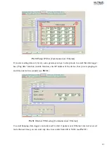
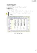
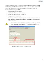
TCP port;
•
UART – where terminal device is connected;
•
Stack depth – number of records keaped in stack from 1 to 10;
•
Connection - number of connections, that
d
ata logger will accept from 1 to 4;
•
Socket life time(s) – time before socket will be closed from 10 to 65535 seconds.
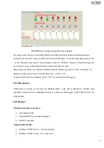
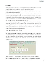
In status window with colors are indicated current status – Green for active, Grey for passive
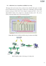
Pic 43
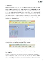
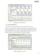
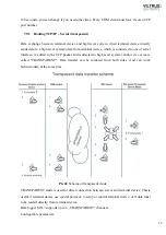
Routing TCP/IP-serial (transparent)
Using TRANSPARENT mode you access directly UART. To each TRANSPARENT channel can
be established from up to 4 computers (PC).
Data logger's answer, to request of one PC, will be sent to all to channel
connected PC's. Even if request was sent from other PC.
7.9.3
Modbus TCP/IP routing
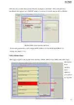
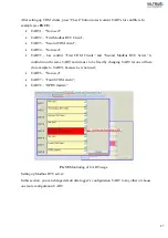
Is used for setting up Modbus TCP/IP routing.
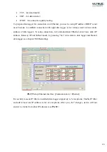
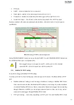
To setup, you must to chose routing type (only one type can be used) – Modbus address or TCP
port:
•
Modbus addresses routing is used for range of addresses routing to Modbus RTU Client.
This is used to route all data, that Modbus RTU address is in set range. If you know address
of external Modbus RTU device, that is connected to Master
d
ata logger, then connecting
through Ethernet or GPRS you can assign connected devices (this can be any device,
connected to
d
ata logger through Modbus RTU client).
•
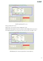
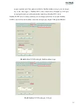
TCP port routing – route data, depending on TCP port. For each Modbus RTU client
Summary of Contents for MX-7
Page 1: ...2 ...
Page 4: ...5 9 6 USB cable 85 9 7 Installing VILTRUS USB driver 85 9 8 TCP IP settings 87 ...
Page 22: ...23 see Pic 6 3 6 V 5 V 6V 8 V 10 V Pic 6 Power for external device DIP switch ...
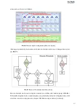
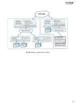
Page 53: ...54 Pic 48 Routing configuration example ...
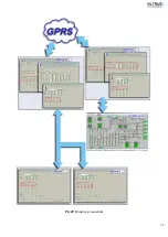
Page 54: ...55 Pic 49 Routing screenshots ...
Page 59: ...60 2 Set COM port number UART port must be configured and assigned to COM client on ...
Page 66: ...67 Pic 61 Setting up RAY 1 as External module by example ...
Page 75: ...76 Pic 71 Records in archives section Archives Configutation ...

