83
9.4
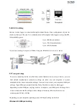
RS232 cabling
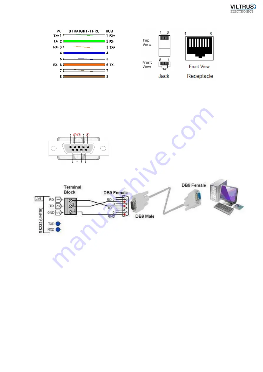
Devices to data logger is connected through terminal blocks. Exact configuration of pins are
shown on the top of the case. For communication with computer data logger is using only RD,
TD and GND signals:
2
pin – RD (Received data)
3
pin – TD (Transmitted data)
5 pin – GND (Ground)
You can use existing Com port, or USB to Com port, PCMCIA to Com or etc. device.
9.5
Com port setup
If you are connecting for the very first time or after hardware reset, on top of device, you can
find default manufacturers connection settings (in other case ask integrator or system
administrator for current connection settings). You need to set correct your computers COM port
settings - Speed (Bits per second), Data bits, Parity, Stop bits to connect to data logger.
Depending on what USB port you plug in device or adapters, your COM port will change. Here
is how to find out what the setting is and to change if necessary. Often such devices use
common ports COM1 - COM8.
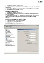
Depending on your computers operating system, COM port setting can be find:
Windows 98 COM port setting
Summary of Contents for MX-7
Page 1: ...2 ...
Page 4: ...5 9 6 USB cable 85 9 7 Installing VILTRUS USB driver 85 9 8 TCP IP settings 87 ...
Page 22: ...23 see Pic 6 3 6 V 5 V 6V 8 V 10 V Pic 6 Power for external device DIP switch ...
Page 53: ...54 Pic 48 Routing configuration example ...
Page 54: ...55 Pic 49 Routing screenshots ...
Page 59: ...60 2 Set COM port number UART port must be configured and assigned to COM client on ...
Page 66: ...67 Pic 61 Setting up RAY 1 as External module by example ...
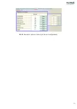
Page 75: ...76 Pic 71 Records in archives section Archives Configutation ...

