


119
A
Appliance fuses..................................94
Appliance too noisy............................94
Appropriate use..................................10
B
Boiler water temperature sensor
■ Curve..............................................93
Brine/water heat pump.......................10
Buffer temperature sensor
■ Curve..............................................93
C
Cascade
■ Number of lag heat pumps.......87, 88
■ Switching method...........................87
■ Use of heat pump.....................87, 88
Central fault message........................85
Checking
■ Sensors..........................................93
Checking for tightness.......................78
Checking fuses..................................94
Checking sensors..............................93
Checking the refrigerant circuit for
leaks...................................................77
Checking the system pressure...........78
Circulation pump for cylinder heating.83
Circulation pump for DHW reheating. 84
Closing the heat pump.......................73
Coding level 1....................................79
Coefficient of performance...............112
Commissioning....................76, 80, 116
Commissioning order.......................116
Commissioning wizard.......................79
Communication module LON.......33, 67
Connecting sensors...........................64
Connecting temperature sensors.......64
Connecting the primary circuit...........46
Connecting the secondary circuit.......47
Connections...............................19, 115
■ Hydraulic.........................................42
■ Primary circuit.................................46
■ Secondary circuit............................47
Connections, main PCB
■ 230 V components..........................52
Connection values
■ Function components.....................54
Controller and sensor PCB..........51, 64
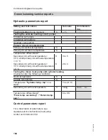
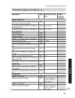
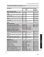
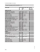
Control parameter reports................106
Control unit door................................94
Cooling capacity...............................112
Cooling circuit flow temperature sensor
■ Curve..............................................93
Curve
■ Temperature sensor, type Pt 500...93
■ Temperature sensor type Ni 500....93
Cylinder primary pump.......................83
Cylinder temperature sensor
■ Curve..............................................93
D
Declaration of Conformity........117, 118
DHW circulation pump.......................83
DHW cylinder
■ Interface..........................................35
■ With primary store system..............36
DHW heating......................................36
Dimensions................................19, 115
Draining..............................................92
Draining the heat pump......................92
E
Electrical components........................89
Electrical connection....................51, 94
■ General information........................11
■ Heat pump control unit.............50, 94
Electrical connections........................50
■ Overview.........................................50
■ Routing cables................................48
Electrical installation scheme
■ Primary circuit, brine/
water25, 26, 28, 30, 31, 32, 33, 35, 37
Electrical Power consumption..........112
Electric booster heater
■ Parameter settings.........................86
Electronic expansion valve................91
Keyword index
Keyword index
5772 458 GB


