64
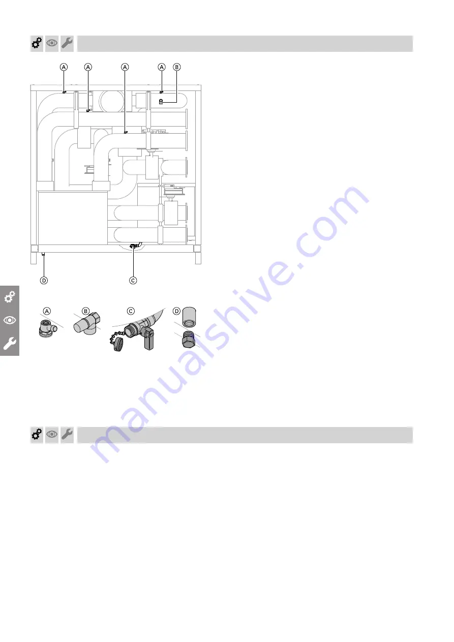
Fig. 39
A
Air vent valve
B
Safety valve
C
Fill/drain valve 3/4'' male thread
D
Drip tray drain connector 3/4'' male thread
1.
Check flange connections on the hydraulic module
for leaks.
2.
Open any non-return valves installed on site.
3.
Check the pre-charge pressure of the expansion
vessel.
4.
Fill (flush) and vent the hydraulic module defrost
box.
!
Please note
Leaking hydraulic connections lead to appli-
ance damage.
■
Check the internal and on-site hydraulic
connections for leaks.
■
In the event of leaks, switch OFF the appli-
ance immediately. Drain the appliance and
check the seating of the seals.
Always
replace damaged or displaced seal rings.
5.
Check the system pressure and top up with water/
glycol if required.
Minimum system pressure: 0.8 bar (80 kPa)
Permiss. operating pressure: 6 bar (0.6 MPa)
Filling and venting on the secondary side
!
Please note
Commissioning when the secondary circuit is
empty causes appliance damage.
Fill and vent the secondary circuit before con-
necting the power supply.
Note
Before
filling the system, observe VDI 2035 part 1.
1.
Check the Victaulic connections in the heat pump
for tightness. The Victaulic couplings must be form-
locked and fitted together seamlessly.
2.
Open any on-site non-return valves if installed.
3.
Check the pre-charge pressure of the expansion
vessel.
4.
Fill (flush) and vent the secondary circuit.
!
Please note
Leaking hydraulic connections lead to appli-
ance damage.
■
Check tightness of the internal and on-site
hydraulic connections.
■
In the event of leaks, switch OFF the appli-
ance immediately. Drain the secondary cir-
cuit and check the seating of the seals.
Always
replace damaged or displaced
seal rings.
5.
Check the system pressure and top up with water if
required.
Minimum system pressure: 0.8 bar (80 kPa)
Permiss. operating pressure: 6 bar (0.6 MPa)
Commissioning, inspection, maintenance
Fill and vent hydraulic module defrost box (if…
(cont.)
5837251


