Call Recorder Single Digital manual ©Vidicode 2011-2014
18
2.3
Connecting the digital lines
As explained in the introduction, the Call Recorder Single Digital works
in pass through mode where it is processing the complete data stream.
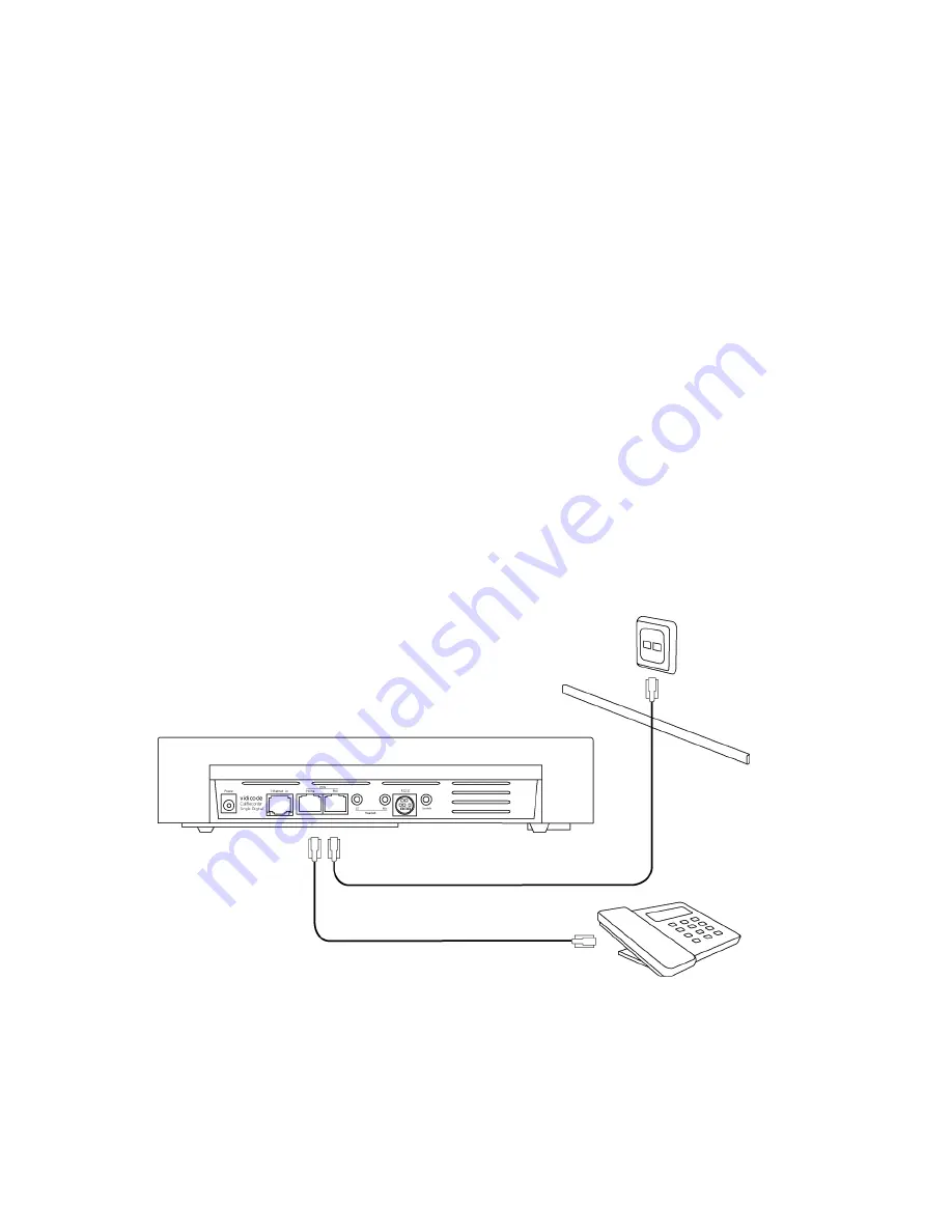
The figure below is an example of a possible setup of the recorder.
2.3.1
Connecting to a single telephone
Most often the Single Digital will be used to record conversations of just
one single telephone, and be placed on the same desktop as the
telephone. This must be a telephone that operates on a digital line.
It doesn't matter if the telephone is using a four-wire (S0) protocol or a
two-wire digital telephony (Up0) protocol, in both cases the Single
Digital is connected in the same way. The line coming from your PBX is
plugged into the PBX connector (4 of page 4), and the Phone connector
(3 of page 4) is connected to your digital telephone.
Connectors 3 and 4 accept both S0 (RJ-45) and Up0 (RJ-11) connectors.
Because the electrical interface is different the Single Digital must first
be configured for the correct interface setting, see § 0. If you connect
the wires the wrong way the Single Digital will periodically emit beeps
displaying the message “Line disconnected!”.
If the Single Digital is turned off, the telephone is turned off as well.
When using a two-wire digital Up0 or the four-wire S0 system, several
protocols could be in use. If you configure the wrong protocol your
telephone might still work but the conversations might not be recorded.
Note
Note
Note
Note: The Single Digital is only compatible with two-wire digital
telephones that adhere to the Up0 standard.
Summary of Contents for SD2750
Page 1: ...Call Recorder Single Digital Manual V2 V2 V2 V2 1 1 1 1 VC20 VC20 VC20 VC2003 03 03 03...
Page 2: ...Call Recorder Single Digital manual Vidicode 2011 2014 2...
Page 11: ...Call Recorder Single Digital manual Vidicode 2011 2014 11 13 3 Liability 67 14 Index 68...
Page 12: ...Call Recorder Single Digital manual Vidicode 2011 2014 12...


