videotronic HQ-IDC-23012P Operating Instructions Manual Download Page 29

Configuration

29

HQ−IDC−23012P
Order No. M578527AC/112003

© 2003 videotronic gmbh
ALL RIGHTS RESERVED

3.2.6

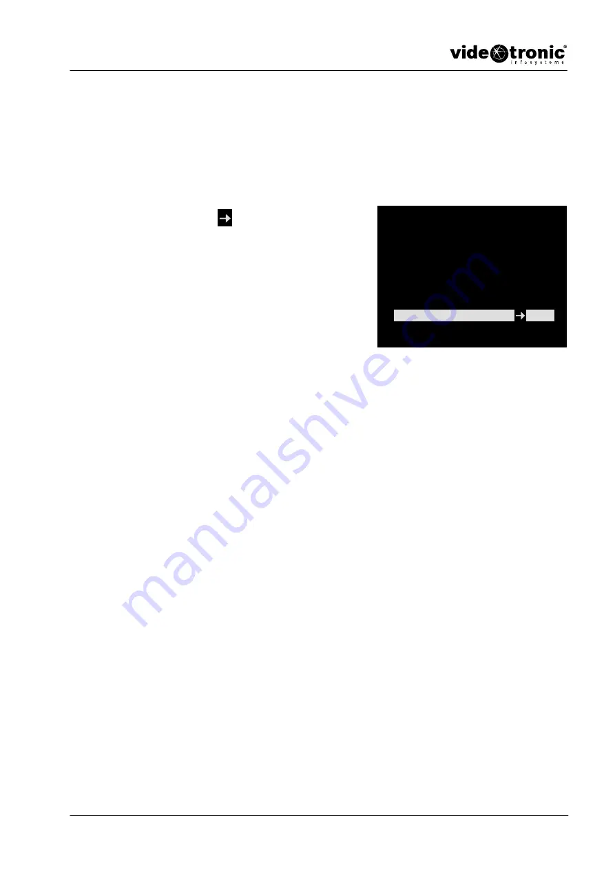
AGC (Automatic Gain Control)

In this menu you can activate the automatic gain control. The function can
regulate fluctuations in brightness, such as occur in normal rooms. The
automatically controlled aperture (auto iris see Chapter 3.2.3) is then generally
not necessary.

Move the arrow 

 with the 

<Down>

 key

to the 

<AGC>

 menu.

Press the 

<ENTER>

 key to open up the

input mode.

Press the 

<UP>

 or 

<DOWN> 

keys to

change the value.

You can choose from 9 different values.
BASE; 1...7 dB; MAX.

Press the 

<ESC>

 key to quit the menu.

This will take you back to the setup menu.

Fig. 24

AGC

SETUP MENU [1/4]

CAMERA ID

ON.

SENSE UP

OFF

AISHUT

AUTO.

AES

FIX.

BLC

OFF

AGC

+7

Summary of Contents for HQ-IDC-23012P

Page 1: ...Instructions for a 1 4 Colour CCD Camera 1 HQ IDC 23012P Order No M578527AC 112003 2003 videotronic gmbh ALL RIGHTS RESERVED Operating Instructions for a 1 4 Colour CCD Camera HQ IDC 23012P Article N...

Page 2: ...Operating Instructions for a 1 4 Colour CCD Camera 2 HQ IDC 23012P Order No M578527AC 112003 2003 videotronic gmbh ALL RIGHTS RESERVED...

Page 3: ...like to thank you very much for your confidence and ask you to kindly read the following instructions carefully before commissioning and operation in order to take full advantage of all the quality fe...

Page 4: ...2 1 Connecting the Monitor to the VIDEO OUT socket of the camera 18 2 3 Mains connection 18 3 Configuration 20 3 1 Key Functions 20 3 2 SETUP MENU 21 3 2 1 Camera ID 22 3 2 2 Sense up 24 3 2 3 AISHUT...

Page 5: ...BNC Connector 53 4 7 Description of the Protocol for the RS232 Interface 55 4 7 1 Outline 55 4 7 2 Serial communication I F 55 4 7 2 1 Connection of a controller and a camera 55 4 7 2 2 Communication...

Page 6: ...Contents 6 HQ IDC 23012P Order No M578527AC 112003 2003 videotronic gmbh ALL RIGHTS RESERVED...

Page 7: ...ronic gmbh ALL RIGHTS RESERVED General Information 1 General Information 8 1 1 Symbols and their Meaning 8 1 2 Information 8 1 3 Safety Precautions 9 1 4 Description of Functions 11 1 5 Overview 12 1...

Page 8: ...se to the action you perform is indicated by an arrow Lists are introduced by a dash 1 2 Information This device has been tested and found to comply with the limits for a Class A digital device pursua...

Page 9: ...or may result in other hazards 4 Do not touch the plug with wet hands Risk of electric shock 5 Do not take the camera apart Risk of fire explosion or electric shock 6 Do not use the camera in the vic...

Page 10: ...ids may contain minerals that result in corrosion of electronic components Note If the camera is exposed to headlights or reflections from strong light smearing or glare may occur Before connecting th...

Page 11: ...s A picture integration facility enables the light sensitivity to be raised by an additional factor of 64 Certification of the camera to the UVV Kassen regulations guarantees a high standard of qualit...

Page 12: ...d for configuration see Chapter 3 1 D Manual adjustment of the focus FAR lens set for infinity NEAR lens set up for close objects E Manual adjustment of the zoom WIDE wide angle recordings TELE zoom F...

Page 13: ...s for interior use RAL 7035 grey beige Video BNC connector BNC C crimped for coaxial cables KA 75 75 ohm coaxial cable 0 6 3 7 grey beige 1 7 Supply Schedule 1 4 colour CCD camera HQ IDC 22012P With i...

Page 14: ...General Information 14 HQ IDC 23012P Order No M578527AC 112003 2003 videotronic gmbh ALL RIGHTS RESERVED 1 8 Declaration of Conformity Fig 3 Declaration of Conformity...

Page 15: ...Device 15 HQ IDC 23012P Order No M578527AC 112003 2003 videotronic gmbh ALL RIGHTS RESERVED Connecting the Device 2 Connection 16 2 1 Camera Installation 16 2 2 Connection to the Monitor 17 2 3 Mains...

Page 16: ...bottom of the camera to fasten it Installation on a wall bracket Push the fastening screw A through the hole in the wall bracket and screw it into the threaded hole B on the underside of the camera In...

Page 17: ...original operating instructions for the monitor Note To transmit the video signal a coaxial cable 75 is normally installed between the camera and the monitor The maximum transmission distance without...

Page 18: ...If you have an intermediate device set the 75 Hi Z selection switch as shown below 2 3 Mains connection Caution Risk of damage and injury Only connect the camera to the mains after installation is com...

Page 19: ...iguration 19 HQ IDC 23012P Order No M578527AC 112003 2003 videotronic gmbh ALL RIGHTS RESERVED Configuration 3 Configuration 20 3 1 Key Functions 20 3 2 SETUP MENU 21 3 3 Using the Remote Control Plug...

Page 20: ...3 1 Key Functions UP A You can use this key to move the cursor upwards and to the right in the menus ENTER B Use this key to open the main menu and any submenus you need You also use it to confirm the...

Page 21: ...3 2 9 DIGITAL ZOOM see Chapter 3 2 10 FOCUS see Chapter 3 2 11 AUTO FOCUS see Chapter 3 2 12 POSITION see Chapter 3 2 13 CAMERA ID Title see Chapter 3 2 1 Fig 10 Setup menu SENSE UP see Chapter 3 2 2...

Page 22: ...he arrow A is located on the position for the first character Press the ENTER key to enter the first character The selection menu opens Move the cursor bar to the character you want with the UP or DOW...

Page 23: ...ion of the camera name on the screen Move the arrow with the Down key to the Position submenu Press the ENTER key to open up the input mode Select the text position with the UP or DOWN keys The text a...

Page 24: ...mber of frames is used very fast moving objects may not be seen on the monitor Move the arrow with the Down key to the SENSE UP menu Press the ENTER key to open up the input mode You can choose from 9...

Page 25: ...he ENTER key to enter the input mode of the submenu selected Auto In this submenu you activate the auto iris function The amount of light transmitted to the camera is controlled automatically FIX This...

Page 26: ...ER key to enter the input mode of the submenu selected Auto In this submenu you activate the automatic control function for the electronic shutter Note Setting 7 corresponds to a short exposure time S...

Page 27: ...his effect Move the arrow with the Down key to the BLC menu Press the ENTER key to open up the input mode Press UP or DOWN to change the selection from OFF to ON Press the ENTER key to access the subm...

Page 28: ...e next area you wish to select using the UP or DOWN keys and press the ENTER key Select all zones using the method described above Press the ESC key to quit the submenu LEVEL In this menu you can vary...

Page 29: ...l rooms The automatically controlled aperture auto iris see Chapter 3 2 3 is then generally not necessary Move the arrow with the Down key to the AGC menu Press the ENTER key to open up the input mode...

Page 30: ...ve to activate the automatic white balance if you are installing the camera in an artificially lighted room Move the arrow with the Down key to the WHITE BAL menu Press the ENTER key to open the input...

Page 31: ...the ENTER key to open the input mode Press the UP or DOWN keys to change the settings between MIN and MAX Press the ESC key to quit the submenu Move the arrow with the Down key to the B Y GAIN menu Pr...

Page 32: ...E zoom Move the arrow with the Down key to the ZOOM menu Press the ENTER key to open the input mode Press the UP or DOWN keys to alter the setting Your settings will be visible in the status bar Press...

Page 33: ...menu 3 2 11 FOCUS In this menu you can activate the focus settings You can set the lens for close objects NEAR or change the lens to the infinity setting FAR Move the arrow with the Down key to the FO...

Page 34: ...f field is adjusted automatically for moving objects Move the arrow with the Down key to the AUTO FOCUS menu Press the ENTER key to open the input mode Press UP or DOWN to change the selection from OF...

Page 35: ...Chapter Move the arrow with the Down key to the POSITION menu Press the ENTER key to open the input mode Press the UP or DOWN keys to open the corresponding submenu SAVE In this menu you can allocate...

Page 36: ...key to quit the submenu ALARM This submenu is where you can allocate one of the stored positions to the alarm input The position will then be loaded according to your allocation when an alarm is rece...

Page 37: ...the ESC button to quit the menu This will take you back to the setup menu 3 2 15 V GAIN Vertical Aperture Correction In this menu you can improve the vertical image quality aperture Move the arrow wi...

Page 38: ...DOWN keys to open the corresponding submenu AREA In this submenu you can specify the area in which a movement will lead to an alarm Press the ENTER key to open the input mode Move the flashing zone in...

Page 39: ...ress the ESC key to quit the submenu TIME In this menu you can adjust the duration of the Motion text message on the monitor Press the ENTER key to open the input mode Press the UP or DOWN keys to set...

Page 40: ...INT or EXT INT If this option is selected an internal signal is registered AGC or Sense up The camera switches automatically from the colour to the black and white mode Note If you have selected shor...

Page 41: ...isable OFF the function Press the ESC button to quit the menu 3 2 19 PRESET In this menu you can reset the camera to the factory settings Move the arrow with the Down key to the PRESET menu Press the...

Page 42: ...the ESC button to quit the menu 3 2 21 FREEZE MODE In this menu you can save the settings for the freeze function see Chapter 3 2 20 You can switch between frame and field display Move the arrow with...

Page 43: ...NTER key to open the input mode H REVERS In this submenu you can enable the horizontal picture inversion function Press the UP or DOWN keys to toggle between the enable ON and disable OFF functions Pr...

Page 44: ...ver without activating the gain Press the UP or DOWN keys to select the appropriate function Press the ESC button to quit the menu MASK A In this submenu you can fade out an area on the monitor screen...

Page 45: ...o open the input mode Press the UP or DOWN keys to alter the vertical position of the area Press the ESC key to quit the submenu Move the arrow with the Down key to the H SIZE submenu Press the ENTER...

Page 46: ...e UP or DOWN keys to alter the horizontal size of the area Press the ESC key to quit the submenu MASK B This submenu allows you to fade out a second area on the monitor screen Proceed as in the MASK A...

Page 47: ...S RESERVED 3 3 Using the Remote Control Plug If you connect a remote control plug to REMOTE you will have access to the SETUP MENU via a remote control Caution You will have to disconnect the electric...

Page 48: ...er No M578527AC 112003 2003 videotronic gmbh ALL RIGHTS RESERVED 3 3 1 Connection Identification Pin no Signal 01 GND 02 RXD 03 TXD 04 IRIS 05 IRIS 06 FOCUS 07 FOCUS 08 ZOOM 09 ZOOM 10 TXTVD 11 EXTVD...

Page 49: ...RESERVED Annex 4 Annex 50 4 1 Technical Specifications for the Product 50 4 2 Troubleshooting 51 4 3 Dimensions 51 4 4 Technical Support 52 4 5 Maintenance and Care 52 4 6 Crimping a BNC Connector 53...

Page 50: ...circuits for Colour switch off IR day and night function automatic manual via OSD menu Antiblooming yes Gain Pedestal yes White balance ATW ATB FIX 3200 9600 K Scanning system NTSC PAL Communication t...

Page 51: ...gh change camera location or activate the backlight function of the camera Blurred video picture Focus not correctly adjusted Heating device in camera housing is faulty when used outdoors fogging on f...

Page 52: ...ting to clean or service it For reasons of electrical safety never clean the device with water or other liquid substances and never put the device under water Only use a soft dry cloth for cleaning th...

Page 53: ...dip about 10 cm of the coaxial cable into methylated spirits Now slide the rubber cap with the smaller diameter first about 10 cm onto the cable and the crimping sleeve for about 5 cm Now strip the i...

Page 54: ...ping tool crimp the two parts together Slide the rubber cap up against the connector housing 3 Assembling and crimping the Type BNC C3 connector Place the contact pin over the core of the coaxial cabl...

Page 55: ...g 23X auto focus camera by RS232 C from a controller By this communication I F zoom focus white balance etc can perform adjustment of a camera from a controller 4 7 2 Serial communication I F 4 7 2 1...

Page 56: ...Command sequence is transmitted further A controller is Response sequence If it receives please transmit 6 ACK to a camera Any further communication are repeat form step 3 6 RS 485 correspondence Sin...

Page 57: ...munication flow and 6 ACK A camera does not transmit 4 ACK 4 7 2 3 Communication data format 1 ENQ Data length 1byte 05h 2 ACK OK Data length 1byte 06h 3 NAK Error Data length 1byte 15h 4 Command sequ...

Page 58: ...D6 D7 D8 D9 D10 D11 D12 D13 D14 D15 ETX SUM D5 D15 Unquestioned Response sequence STX A0h 40h 01h 00h D5 D6 D7 D8 D9 D10 D11 D12 D13 D14 D15 ETX SUM D5 The 1st character High byte data D6 The 1st char...

Page 59: ...character Low byte data D11 The 9th character High byte data D12 The 9th character Low byte data D13 The 10th character High byte data D14 The 10th character Low byte data D15 Unfixed 3 CAMERA ID The...

Page 60: ...data D6 The 16th character Low byte data D7 The 17th character High byte data D8 The 17th character Low byte data D9 The 18th character High byte data D10 The 18th character Low byte data D11 The 19th...

Page 61: ...High byte data D6 The 1st character Low Byte data D7 The 2nd character High byte data D8 The 2nd character Low Byte data D9 The 3rd character High byte data D10 The 3rd character Low Byte data D11 The...

Page 62: ...13 The 10th character High byte data D14 The 10th character Low Byte data D15 Unquestioned Response sequence STX A0h 40h 01h 01h D5 D6 D7 D8 D9 D10 D11 D12 D13 D14 D15 ETX SUM D5 D15 Unfixed 8 CAMERA...

Page 63: ...character High byte data D10 The 18th character Low Byte data D11 The 19th character High byte data D12 The 19th character Low Byte data D13 The 20th character High byte data D14 The 20th character Lo...

Page 64: ...D14 D15 ETX SUM D5 D15 Unfixed 11 CAMERA ID DISPLAY WRITE Command sequence STX 21h 40h 00h D4 D5 D6 D7 D8 D9 D10 D11 D12 D13 D14 D15 ETX SUM D4 00h OFF 01h ON D5 D15 Unquestioned Response sequence STX...

Page 65: ...14 D15 ETX SUM D4 Unfixed D5 PRIORITY 00h AGC 01h SENS D6 AGC D7 SENSE UP D8 D15 Unfixed 2 AGC WRITE Command sequence STX 21h 41h 01h D4 D5 D6 D7 D8 D9 D10 D11 D12 D13 D14 D15 ETX SUM D4 AGC Setting v...

Page 66: ...ned Response sequence STX A0h 41h 04h D4 D5 D6 D7 D8 D9 D10 D11 D12 D13 D14 D15 ETX SUM D4 D15 Unfixed 4 7 3 3 AI SHUT AES 1 AISHUT AES READ Command sequence STX 31h 42 h 00h D4 D5 D6 D7 D8 D9 D10 D11...

Page 67: ...3 AI SHUT AUTO LEVEL WRITE Command sequence STX 21h 42 h 01h D4 D5 D6 D7 D8 D9 D10 D11 D12 D13 D14 D15 ETX SUM D4 AISHUT AUTO LEVEL 00h MIN 08h MAX D5 D15 Unquestioned Response sequence STX A0h 42 h 0...

Page 68: ...6 AES AUTO LEVEL WRITE Command sequence STX 21h 42 h 04h D4 D5 D6 D7 D8 D9 D10 D11 D12 D13 D14 D15 ETX SUM D4 AES AUTO LEVEL 00h MIN 08h MAX D5 D15 Unquestioned Response sequence STX A0h 42 h 04h D4...

Page 69: ...00h MIN 07h MAX D7 BLC AREA The 1st step Each bit 0 OFF 1 ON D8 BLC AREA The 2nd step Each bit 0 OFF 1 ON D9 BLC AREA The 3rd step Each bit 0 OFF 1 ON D10 BLC AREA The 4th step Each bit 0 OFF 1 ON D1...

Page 70: ...43h 02h D4 D5 D6 D7 D8 D9 D10 D11 D12 D13 D14 D15 ETX SUM D4 BLC AREA The 1st step Each bit0 OFF 1 ON D5 BLC AREA The 2nd step Each bit0 OFF 1 ON D6 BLC AREA The 3rd step Each bit0 OFF 1 ON D7 BLC ARE...

Page 71: ...D10 D15 Unfixed 2 WHITE BALANCE WRITE Command sequence STX 21h 44h 00h D4 D5 D6 D7 D8 D9 D10 D11 D12 D13 D14 D15 ETX SUM D4 WHITE BALANCE 00h ATW 01h AWB D5 D15 Unquestioned Response sequence STX A0h...

Page 72: ...It is the same as 1 5 R Y GAIN WRITE Command sequence STX 21h 44h 03h D4 D5 D6 D7 D8 D9 D10 D11 D12 D13 D14 D15 ETX SUM D4 R Y GAIN 00h MIN 08h MAX D5 D15 Unquestioned Response sequence STX A0h 44h 0...

Page 73: ...IN 1 H GAIN V GAIN READ Command sequence STX 31h 47h 00h D4 D5 D6 D7 D8 D9 D10 D11 D12 D13 D14 D15 ETX SUM D4 D15 Unquestioned Response sequence STX A0h 47h 00h D4 D5 D6 D7 D8 D9 D10 D11 D12 D13 D14 D...

Page 74: ...SUM It is the same as 1 4 7 3 7 LENS ZOOM FOCUS DIGITAL ZOOM AUTO FOCUS 1 LENS READ Command sequence STX 31h 45h 00h D4 D5 D6 D7 D8 D9 D10 D11 D12 D13 D14 D15 ETX SUM D4 D15 Unquestioned Response sequ...

Page 75: ...e STX A0h 45h 01h D4 D5 D6 D7 D8 D9 D10 D11 D12 D13 D14 D15 ETX SUM It is the same as 1 4 ZOOM STOP Command sequence STX 21h 45h 02h D4 D5 D6 D7 D8 D9 D10 D11 D12 D13 D14 D15 ETX SUM D4 D15 Unquestion...

Page 76: ...D7 D8 D9 D10 D11 D12 D13 D14 D15 ETX SUM D4 D15 Unquestioned Response sequence STX A0h 45h 05h D4 D5 D6 D7 D8 D9 D10 D11 D12 D13 D14 D15 ETX SUM It is the same as 1 8 DIGITAL ZOOM Command sequence ST...

Page 77: ...ned Response sequence STX A0h 45h 0Ah D4 D5 D6 D7 D8 D9 D10 D11 D12 D13 D14 D15 ETX SUM It is the same as 1 11 FOCUS STEP Specification Command sequence STX 21h 45h 0Bh D4 D5 D6 D7 D8 D9 D10 D11 D12 D...

Page 78: ...STX A0h 45h 0Eh D4 D5 D6 D7 D8 D9 D10 D11 D12 D13 D14 D15 ETX SUM It is the same as 1 14 FOCUS 1STEP NEAR Command sequence STX 21h 45h 14h D4 D5 D6 D7 D8 D9 D10 D11 D12 D13 D14 D15 ETX SUM D4 D15 Unqu...

Page 79: ...OM 1STEP WIDE Command sequence STX 21h 45h 17h D4 D5 D6 D7 D8 D9 D10 D11 D12 D13 D14 D15 ETX SUM D4 D15 Unquestioned Response sequence STX A0h 45h 17h D4 D5 D6 D7 D8 D9 D10 D11 D12 D13 D14 D15 ETX SUM...

Page 80: ...SUM D4 Unfixed D5 It is registered ZOOM High Byte D6 It is registered ZOOM Low Byte D7 It is registered FOCUS High Byte D8 It is registered FOCUS Low Byte D9 D15 Unfixed 3 POSITION READ3 Command sequ...

Page 81: ...ed Response sequence STX A0h 46h 01h D4 D5 D6 D7 D8 D9 D10 D11 D12 D13 D14 D15 ETX SUM It is the same as 1 5 POSITION DATA LOAD Command sequence STX 21h 46h 02h D4 D5 D6 D7 D8 D9 D10 D11 D12 D13 D14 D...

Page 82: ...D7 D8 D9 D10 D11 D12 D13 D14 D15 ETX SUM It is the same as 1 8 POSITION OSD Command sequence STX 21h 46h 04h D4 D5 D6 D7 D8 D9 D10 D11 D12 D13 D14 D15 ETX SUM D4 POSITION OSD 00h OFF 01h ON D4 D15 Unq...

Page 83: ...D7 D8 D9 D10 D11 D12 D13 D14 D15 ETX SUM D4 Undefined D5 MOT DETECTION 00h OFF 01h ON D6 MOT LEVEL 00h MIN 09h MAX D7 MOT AREA The 1st step Each bit0 OFF 1 ON D8 MOT AREA The 2ndstep Each bit0 OFF 1...

Page 84: ...48h 01h D4 D5 D6 D7 D8 D9 D10 D11 D12 D13 D14 D15 ETX SUM D4 MOT LEVEL 00h MIN 09h MAX D5 D15 Unquestioned Response sequence STX A0h 48h 01h D4 D5 D6 D7 D8 D9 D10 D11 D12 D13 D14 D15 ETX SUM It is the...

Page 85: ...7 D8 D9 D10 D11 D12 D13 D14 D15 ETX SUM D4 MOT TIME 00h 10sec 01h 30sec 02h 60sec D5 D15 Unquestioned Response sequence STX A0h 48h 03h D4 D5 D6 D7 D8 D9 D10 D11 D12 D13 D14 D15 ETX SUM It is the same...

Page 86: ...ed D5 PRESET Flag 00h CANSEL 01h OK D6 INITIAL 00h OFF 01h ON D7 H REVERS 00h OFF 01h ON D8 V REVERS 00h OFF 01h ON D9 NEGATIVE 00h OFF 01h ON D10 SYNC 00h VSYNC 01h INTERNAL D11 PHASE LEVEL High Byte...

Page 87: ...t is the same as 1 4 H REVERS WRITE Command sequence STX 21h 4Fh 02h D4 D5 D6 D7 D8 D9 D10 D11 D12 D13 D14 D15 ETX SUM D4 H REVERS 00h OFF 01h ON D5 D15 Unquestioned Response sequence STX A0h 4Fh 02h...

Page 88: ...1 7 SYNC WRITE Command sequence STX 21h 4Fh 05h D4 D5 D6 D7 D8 D9 D10 D11 D12 D13 D14 D15 ETX SUM D4 SYNC 00h VSYNC 01h INTERNAL D5 D15 Unquestioned Response sequence STX A0h 4Fh 05h D4 D5 D6 D7 D8 D9...

Page 89: ...SUM It is the same as 1 10 PHASE LEVEL OFFSET WRITE Command sequence STX 21h 4Fh 08h D4 D5 D6 D7 D8 D9 D10 D11 D12 D13 D14 D15 ETX SUM D4 OFFSET High Byte D5 OFFSET Low Byte D6 D15 Unquestioned Respo...

Page 90: ...It is the same as 1 13 OTHER READ2 Command sequence STX 31h 4Fh 01h D4 D5 D6 D7 D8 D9 D10 D11 D12 D13 D14 D15 ETX SUM D4 D15 Unquestioned Response sequence STX A0h 4Fh 01h D4 D5 D6 D7 D8 D9 D10 D11 D1...

Page 91: ...EXT LEVEL 00h MIN A11h MAX D8 IR EXT Logic flag 00h Usual A01h Reversal D9 D15 Undefined 2 IR ON OFF WRITE Command sequence STX 21h 49h 00h D4 D5 D6 D7 D8 D9 D10 D11 D12 D13 D14 D15 ETX SUM D4 IR ON O...

Page 92: ...s 1 5 IR EXT LEVEL WRITE Command sequence STX 21h 49h 03h D4 D5 D6 D7 D8 D9 D10 D11 D12 D13 D14 D15 ETX SUM D4 IR IEXT LEVEL Flag 00h MIN 11h MAX D5 D15 Unquestioned Response sequence STX A0h 49h 03h...

Page 93: ...D12 D13 D14 D15 ETX SUM D4 MASK1 ON OFF 00h OFF 01h ON D5 00h D6 H START 00h FFh D7 H END 00h FFh D8 V START 00h FFh D9 V END 00h FFh D10 D15 Undefined 2 MASK2 READ Command sequence STX 31h 4Ah 01h D...

Page 94: ...D4 is OFF 00h D6 D9 cannot Specification Response sequence STX A0h 4Ah 00h D4 D5 D6 D7 D8 D9 D10 D11 D12 D13 D14 D15 ETX SUM It is the same as 1 4 MASK2 WRITE Command sequence STX 21h 4Ah 01h D4 D5 D6...

Page 95: ...D10 D11 D12 D13 D14 D15 ETX SUM D4 D15 Unquestioned Response sequence STX A0h 4Ch 02h D4 D5 D6 D7 D8 D9 D10 D11 D12 D13 D14 D15 ETX SUM D4 D15 Undefined 3 DOWN SW WRITE Command sequence STX 21h 4Ch 04...

Page 96: ...7 D8 D9 D10 D11 D12 D13 D14 D15 ETX SUM D4D 14 Undefined This function corresponds in the next term VERSION 6 UP DOWN SW WRITE RFEEZE Correspondence Command sequence STX 21h 4Ch 0Ch D4 D5 D6 D7 D8 D9...

Page 97: ...cation flag 00h 1 Pair 1 01h 1 Pair N D7 D14 Undefined 2 RS485 Correspondence ID WRITE Command sequence STX 21h 4Dh 00h D4 D5 D6 D7 D8 D9 D10 D11 D12 D13 D14 D15 ETX SUM D4 ID 00h EFh D5 D14 Unquestio...

Page 98: ...ZE MODE 00h FIELD 01h FRAME D7 D15 Undefined 2 FREEZE WRITE Command sequence STX 31h 4Dh 00h D4 D5 D6 D7 D8 D9 D10 D11 D12 D13 D14 D15 ETX SUM D4 FREEZE 00h OFF 01h ON D5 D14 Unquestioned Response seq...

Page 99: ...K Select 00h MASK1 01h MASK2 D4 D14 Unquestioned Response sequence STX A0h 5Ah D3 D4 D5 D6 D7 D8 D9 D10 D11 D12 D13 D14 ID ETX SUM D3 MASK Select 00h MASK1 01h MASK2 D4 D5 Undefined D6 MASK 00h OFF 01...

Page 100: ...N Start 00h FFh D9 H POSITION End 00h FFh D10 V POSITION Start 00h FFh D11 V POSITION End 00h FFh D12 D14 Unquestioned Response sequence STX A0h 5Ah D3 D4 D5 D6 D7 D8 D9 D10 D11 D12 D13 D14 ID ETX SUM...

Page 101: ...F 01 ON D7 D14 Unquestioned Response sequence STX A0h 5Ah D3 D4 D5 D6 D7 D8 D9 D10 D11 D12 D13 D14 ID ETX SUM It is the same as 1 5 MASK H POSITION WRITE Command sequence STX 21h 5Ah D3 D4 D5 D6 D7 D8...

Page 102: ...TY OF CHANGE 00h FFh D8 D14 Unquestioned Response sequence STX A0h 5Ah D3 D4 D5 D6 D7 D8 D9 D10 D11 D12 D13 D14 ID ETX SUM It is the same as 1 7 MASK H SIZE WRITE Command sequence STX 21h 5Ah D3 D4 D5...

Page 103: ...TX 21h 5Ah D3 D4 D5 D6 D7 D8 D9 D10 D11 D12 D13 D14 ID ETX SUM D3 MASK Select 00h MASK1 01h MASK2 D4 06h D5 EEPROM 00h NO SAVE 01h SAVE D6 POSITION 00h REDUCTION 01h INCREASE D7 THE QUANTITY OF CHANGE...

Page 104: ...FOCUS SPEED 00h MIN 04h MAX D7 D14 Undefined 2 LENS SPEED ZOOM WRITE Command sequence STX 21h 5Bh 00h D4 D5 D6 D7 D8 D9 D10 D11 D12 D13 D14 ID ETX SUM D4 ZOOM SPEED 00h MIN 04h MAX D5 D14 Undefined R...

Page 105: ...Annex 105 HQ IDC 23012P Order No M578527AC 112003 2003 videotronic gmbh ALL RIGHTS RESERVED 4 8 Personal Notes...

Page 106: ...Annex 106 HQ IDC 23012P Order No M578527AC 112003 2003 videotronic gmbh ALL RIGHTS RESERVED...

Page 107: ...Annex 107 HQ IDC 23012P Order No M578527AC 112003 2003 videotronic gmbh ALL RIGHTS RESERVED...

Page 108: ...ALL RIGHTS RESERVED Technical specifications are subject to change without prior notice Printed in Germany German Engineering Design Worldwide CCTV Manufacturer International Service Hotline Tel 49 0...

Reviews: