2-14
VL-1225/6 Analog Input/Output Board
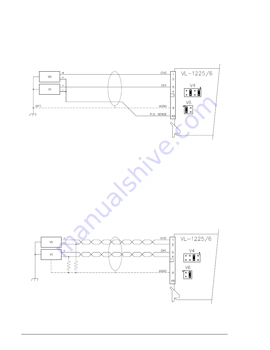
Pseudo-Differential Mode
The pseudo-differential mode is used for signals that are not referenced to ground, but are all connected
to a single common return line. This mode can provide most of the advantages of full differential input
while requiring fewer total wires. In the pseudo-differential mode, 16 input channels can be accommo-
dated.
Figure 2-12. Pseudo-Differential Input Mode
Differential Mode
The differential mode is used for signals that are not referenced to a common or ground point, but simply
have a voltage difference between the two input wires (usually a twisted pair). It is desirable to use the
differential mode in electrically noisy environments since it reduces the effects of electromagnetically
induced noise and ground currents. It is especially useful in eliminating the effects of common mode noise
generated on input lines over longer distances. In the differential mode, only eight input channels are
available.
Note that in full differential operation a return path must be provided for the bias currents of the input
amplifier. This can be accomplished by grounding the voltage source power supply(s) to the VL-1225/6
board, or by installing a 10K to 100K
W
resistor as shown for each channel. These resistors should be
located in close proximity to the voltage source.
Figure 2-13. Differential Input Mode
Configuration – Analog Input Configuration


