SensorDAQ User's Manual
15
1.
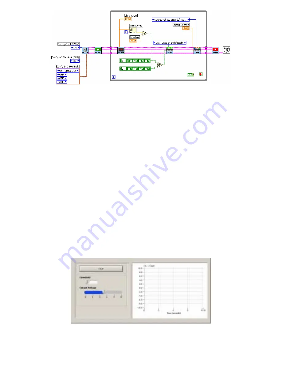
First add the subVI that performs analog output (SensorDAQ_AO.vi). This can be
found in the example called TerminalEx02_AnalogOut.vi or in the SensorDAQ
palette. Open this example and copy and paste the AO subVI into the While Loop
of your program.
2.
Configure the AO subVI to “Output Voltage on Indefinitely”.
3.
All of the output lines from the DIO subVI must be wired into the AO subVI
(the DAQmx Task Cluster, Setup Parameters, and error in).
4.
Go to the front panel, right mouse click to get your front panel functions and
select the Horizontal Pointer Slide. Type in “horizontal pointer slide” in the
Search if you can not find it.
5.
Label this control as “Output Voltage.”
6.
Double-click on the maximum value of this control to highlight and change the
value to 5 (since this control will be controlling the SensorDAQ’s analog output
voltage, which is in the range of 0-5 volts).
7.
Go back to the Block Diagram, find the Output Voltage control, and move it
into the While Loop.
8.
Wire this control into the Output Voltage node of the AO subVI.
Go to the Front panel and set the threshold to 2 and the Output Voltage to 0. Run the
program, and slowly increase the Output Voltage. Watch the graph as the Voltage
Probe reads the voltage. Increase the voltage to a value above 2 and look at the LED
wired to PO.0, it should now be turned on. Click the Stop button to end the program


