SensorDAQ User's Manual
14
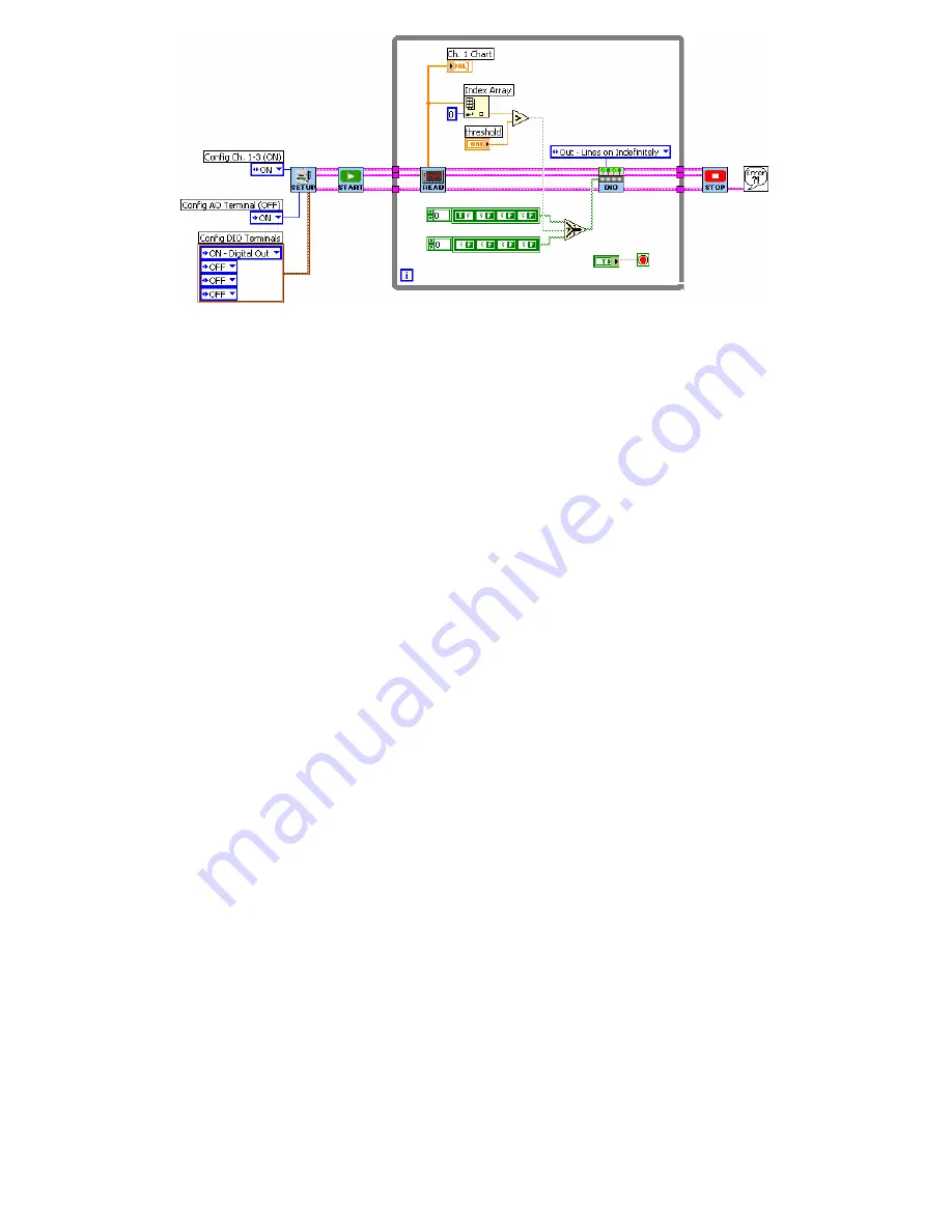
1.
Open example ControlEx01_ControlDigOutWithSensor.vi, found in the
Feedback and Control folder.
2.
Select the SensorDAQ_DIO.vi, the Select function, and the two Boolean arrays
(or get the DIO subVI from the sensorDAQ palette). An easy way to do this is to
hold down the Shift key on your keyboard and click the mouse on the code that
you wish to select.
3.
Copy the selected code.
4.
Go back to your VI and make room in the While Loop by enlarging the Loop.
5.
Paste the selected code into the While Loop of your VI.
6.
Fix any broken wires and wire the result of the Greater? function into the “s”
node of the Select function.
7.
All of the output lines from the Read subVI must be wired into the DIO subVI
(the DAQmx Task Cluster, Setup Parameters, and error in).
8.
Make sure the DIO subVI is configured with “Out-Lines on Indefinitely”.
9.
The DIO subVI requires an array of four Boolean elements as an input, to tell it
which lines are turned on and which are turned off. The first element in the array
sets the On/Off state of PO.0; the second element sets the On/Off state of PO.1,
etc. We want lines PO.1,PO.2, and PO.3 Off at all times, so these elements are
kept False. The first element (PO.0) we want to be True if the Greater? function
returns a True (Analog Output is greater than the threshold); we want it to be
False if Greater? function returns a False. Make sure that two Boolean arrays are
set up this way (where the dark green with white letter represents which state is
active).
Finish the program by adding code to allow the user to control SensorDAQ’s analog
output voltage.


