background image

!


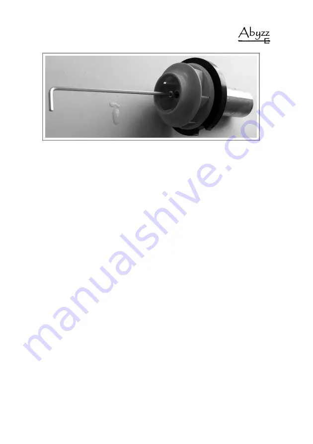
Fig. 5: 

Disassembly of impeller wheel


When assembling the pump (fig. 6 and 7), please make sure that the guide lug (A) fits 
into  the  corresponding  opening  on  the  magnetic  impeller  plate  and  that  the  flushing 
opening  (C)  is  in  the  right  place.  Make  sure  that  the  bearing  (B)  is  in  the  correct 
position  inside  the  motor.  If  necessary,  push  the  bearing  into  position  with  a  blunt 
object  (e.g.  the  handle  of  a  screwdriver).  Make  sure  that  the  O-ring  for  the  vibration 
isolation and sealing (fig. 10) is in the right position before reassembling the pump. 

20

Summary of Contents for Abyzz A400 IPU

Page 1: ...Operating Manual A400 IPU...

Page 2: ...s against venotec in relation to the products described in this manual shall be handled exclusively as per the guarantee conditions of the manufacturer The product specifications may deviate from the...

Page 3: ...formation 8 Installation of driver 9 Installation of pump 10 Commissioning 11 Run in phase 12 Description of control elements 13 Operation 14 Maintenance 17 Guarantee 24 Troubleshooting 26 Disposal 27...

Page 4: ...of this product for as long as possible please read this manual carefully and observe our recommendations Should the quality of the product not meet your expectations please contact the dealer who sol...

Page 5: ...Scope of delivery 1 Abyzz A400 pump with 3m or 10m cable 1 Abyzz A400 driver incl mounted power cord 1 5m 1 Registration form 5...

Page 6: ...ge 0 0 100 0 Precise speed adjustment in steps of 0 1 Integrated programming to generate waves bursts and random flow patterns with additional BOOSTMODE to override actual programming MCFS Menu Contro...

Page 7: ...ciated parts with each other Keep the leads connectors and drivers dry and protect the components from damage Do not work with wet hands on the wiring or on the driver Operate the product only when th...

Page 8: ...mounted below the water level Please always observe the generally applicable national and international regulations during installation The maximum working pressure must not exceed 2 5 bar Prior to st...

Page 9: ...ected load of your supply line under any circumstances Ambient temperature and cooling The product can be used at ambient temperatures of 2 C to 40 C Depending on the required performance the temperat...

Page 10: ...or the safe operation of the pump It has to be made sure that the pump is always filled with the medium completely Abyzz cannot be held responsible for damages to the pump which result from inappropri...

Page 11: ...the Abyzz pump can be put into operation To do this connect the motor connection cable to the driver The plug is coded and can only be connected in one position The plug used meets the highest requir...

Page 12: ...al and does not pose a long term problem During post fabrication testing all pumps are tested for performance concentricity and noise The start up phase can take a few days depending on the operating...

Page 13: ...d The Start Stop setting is automatically saved so that the pump automatically returns to its original operating mode after a loss of operating voltage If you want to enter the menu to display operati...

Page 14: ...operating state e g to stir up dirt If you have selected the operating mode press Start Stop You will then be asked to enter the corresponding data minimum and maximum power time interval Finally conf...

Page 15: ...od Settings No Module S 13 Child Lock OFF S 14 Display Service Info S 15 1 Firmware V3 2 1 0528b 2 41 Boost mode ON 40 42 43 20 Mode Wave UP DOWN SS 20 21 22 23 24 20 Mode Random UP DOWN SS 60 61 62 M...

Page 16: ...sary loosen the retaining screw with a suitable Allen key and pull the impeller off the shaft This screw is made of titanium and must not be replaced by another screw If further disassembly is necessa...

Page 17: ...Fig 1 Pump with pump head A200 17...

Page 18: ...Fig 2 Loosening of impeller components rotor unit Fig 3 Disassemly of impeller components rotor unit 18...

Page 19: ...e up of bearing left If you need to disassemble the impeller wheel use a suitable Allen wrench to undo the retaining screw fig 5 and pull the impeller wheel off the shaft This screw is made of titaniu...

Page 20: ...peller plate and that the flushing opening C is in the right place Make sure that the bearing B is in the correct position inside the motor If necessary push the bearing into position with a blunt obj...

Page 21: ...guide lug and flushing opening O rings and rubber parts suffer from unavoidable aging and should be replaced as required These parts are listed in the spare parts list and can be ordered by stating t...

Page 22: ...ng bracket is flush with the flange Screw the pump head back onto the motor block The screws must be tightened crosswise to create even pressure on the O ring seal and to ensure impermeability Only ha...

Page 23: ...r a lack of intake protection are expressly excluded from guarantee and warranty claims Calcination inside the pump and any resulting damage to the product or motor damage by use as not intended and a...

Page 24: ...s Due to the constant further development of our products and to innovations that in particular serve to improve quality safety and technical progress the manufacturer reserves the right to make techn...

Page 25: ...ot flash a No mains voltage a Check the mains connection If the fault cannot be rectified there is a driver fault In this case please contact the service team Status COMM FU a Control unit communicati...

Page 26: ...or reporting to the EAR Germany registry of old electrical equipment is DE 16546900 If you do not want to dispose of the product through us you must bear the costs of disposing of the product in accor...

Page 27: ...t maximum 12 5 m Rated input 4 400 W Operating voltage 230V 50 60Hz For details see the characteristic curves in the appendix fig 10 et seq The following calibrated devices were used for the measureme...

Page 28: ...Dimensions and weight Dimensions in millimeter Fig 8 Dimensions pump A400 28...

Page 29: ...ct with the medium being conveyed Housing Pump head Impeller wheel ABS GF 20 PA 6 Flushing line PVC PU Shaft WCNi Impeller Titanium grade 2 Screws Titanium grade 2 Bearings SSIC O ring Bearing seat De...

Page 30: ...ng 6 Bearing bracket O ring large 7 Bearing bracket O ring small 8 Bearing seat O ring 2x 9 Bearing 2x 10 Compression bearing rubber seal 11 Compression bearing 12 Rotor 13 Motor block 3m 14 Impeller...

Page 31: ...FIg 11 Flow charts 31...

Page 32: ...relevant provisions EC Directive 2004 108 EU Applied harmonized standards DIN EN 61000 6 1 DIN EN 61000 6 2 DIN EN 61000 6 4 DIN EN 61000 3 2 These devices are Class A devices In residential environme...

Page 33: ...33 WWW ABYZZ DE...

Reviews: