


28
3.4
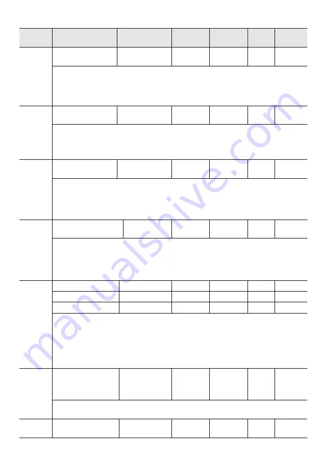
Pn3 Speed Parameters
Function
code
Parameters
Range
Default
Unit
Address
Effective
way
Pn300
Analog speed
command gain
150~3000
600
0.01V/rated 0x0300
INST
Use this parameter to set the analog voltage value (V-REF) required by the speed command to
make the servo motor speed at the rated value
Note: Do not apply voltages above -10 ~ 10V. Exceeding this range may cause damage to the
driver
Pn301
Reversed analog speed
command
0~1
0
-
0x0301
INST
Set the voltage polarity of the analog speed command:
0-positive polarity: positive voltage corresponds to positive speed command 1-negative polarity:
positive voltage corresponds to negative speed command
Pn302
Analog speed
command filter time
0~655.35
0.40
ms
0x0302
INST
The function of applying a delay filter to the analog speed command (V-REF) input once to
smooth the speed command usually does not need to be changed. If the setting value is too large,
the responsiveness may be reduced. Please set while confirming the responsiveness
Pn303
Analog speed command
dead area range
0~3
0
V
0x0303
INST
During analog speed control, even if the input command is 0V, the servo motor may rotate at a
slight speed. This is because the command within the servo unit has a slight deviation, which can
be eliminated by setting an appropriate analog speed command dead band range
Pn304
Pn305
Pn306
Internal speed 1
0~10000
100
rpm
0x0304
INST
Internal speed 2
0~10000
200
rpm
0x0305
INST
Internal speed 3
0~10000
300
rpm
0x0306
INST
/SPD-A /SPD-B speed command
OFF OFF zero speed
OFF ON Internal speed 1
ON ON Internal speed 2
ON OFF Internal speed 3
Pn310
Speed command
trapezoidal acceleration
time
0~10000
0
ms
0x0310
INST
The time required to accelerate the set speed from 0r / min to the maximum speed (corresponding
to the motor model)
Pn311
Speed command
trapezoidal deceleration
0~10000
0
ms
0x0311
INST
Summary of Contents for SD700-110D series
Page 8: ...4 ...
Page 14: ...10 1 10 Position Control Wiring Diagram ...
Page 15: ...11 1 11 Speed Control Wiring Diagram ...


