background image

AC80T Tower Crane Purpose VFD Manual   


36


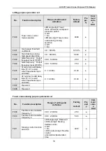
E.oU2 

Dec 

over-voltag

 Deceleration time is 

too short. 

 Load potential energy 

or inertia is too large. 

 Power voltage 

fluctuation over limit. 

 Prolong deceleration time 

properly. 

 Reduce load inertia or 

improve inverter 
capacitance or add 
braking unit.   

 Detect input power and 

clear fault. 


E.oU3 

Constant 

speedover-

voltage 

 Power voltage 

fluctuation over limit. 

 Detect input power voltage 

and eliminate fault. 

 Install input reactor. 


E.oU4 

Over-volta

ge while 

stop 

 Power voltage 

fluctuation over limit. 

 Check input power, 

eliminate fault. 

 Seek support from factory. 


E.oC1 

Acc 

over-curren

 Acceleration time is 

too short. 

 Start running motor. 

 V/F curve setting is not 

suitable. Or torque 
boost too high. 

 Inverter capacitance is 

too small. 

 Prolong acc time. 

 Restart motor until it totally 

stops. Set F1.00 as 1or 2. 

 Reset V/F curve or torque 

boost value. 

 Select inverter with right 

capacitance. 


E.oC2 

Dec 

over-curren

 Deceleration time is 

too short. 

 Load potential energy 

or inertia is too large. 

 Power voltage 

fluctuation over limit. 

 Prolong deceleration time. 


 Connect external braking 

resistance or braking unit. 


 Select inverter with right 

capacitance. 


E.oC3 

Constant 

speedover-

current 

 Sudden load change. 

 Power grid voltage is 

too low. 

 Check load change and 

eliminate it. 

 Check input power, 

eliminate fault. 


E.oL1 

Motor 

over-load 

 V/F curve setting is not 

suitable. Or torque 
boost too high. 

 Power grid voltage is 

too low. 

 Unright overload 

protection setting. 

 Locked-rotor run or 

too heavy load. 

 Universal motor long 

time low speed run. 

 Reset V/F curve or torque 

boost value. 

 Check input power, 

eliminate fault. 

 Unreasonable F5.06 

setting. 

 Adjust load or select 

inverter with right 
capacitance.  

 If need long low-speed 

operation, please choose 
special motor for inverter.

Summary of Contents for AC80T

Page 1: ......

Page 2: ...this product must experience professional skill train must be familiar with installation wiring running and maintain and can rightly deal with emergency cases in use Safety guidance Safety regulations...

Page 3: ...mly Earth must be reliable and earth resistance must be lower than 10 Before opening the inverter please disconnect all related equipment power supply and make sure the mains DC voltage is in safe ran...

Page 4: ...cronding to environmental protection departments 1 2 Technical Specification Items Description Power Input Voltage frequency Three phase 380V 50 60Hz Allowable fluctuations Voltage 320V 440V voltage u...

Page 5: ...me selection frequency setting channel selection external fault alarm External output signal 1 relay output 2 collector output 0 10V output 4 20mA output frequency pulse output Protection function Ove...

Page 6: ...ol to ensure system safety and reliability Tower crane slewing purpose frequency inverter strong load capacity smooth start without shaking fast and efficient in place more reliable performance 1 One...

Page 7: ...t company immediately After checking the product pls also check if the model is the one you ordered The model of the product is on the nameplate MODEL column If the model is not in accodance with your...

Page 8: ...4KW 3PH 380VAC 10A AC80T 5R5 H B 5 5KW 13A AC80T 7R5 H B 7 5KW 17A AC80T 011 H B 11KW 25A AC80T 015 H B 15KW 32A AC80T 018 Q H B 18KW 38A AC80T 022Q 22KW 45A AC80T O30Q 30KW 60A AC80T O37Q 37KW 75A A...

Page 9: ...e Purpose VFD Manual 8 2 4 Dimension W1 W H1 H D1 D Inverter model W W1 H H1 D D1 Mounting diatmeter AC80T 004 H B 159 147 2 246 236 157 5 148 5 5 AC80T 5R5 H B AC80T 7R5 H B 195 179 291 275 167 5 158...

Page 10: ...to requirements make sure to ground the supply neutral for 380V class After opening the manual switch between the drive and motor please wait 10 minutes before inspecting performing maintenance or wir...

Page 11: ...voltage has fallen to safe level After that pls wait for 5mins and then continue the relevant operation The inverter s control cable power cable and the connecting cable of the motor must be isolated...

Page 12: ...ort circuit at factory Brake sticking output Fault output Third speed Fourth speed Fifth speed Precautions 1 Multi functional input terminal X1 X8 can choose NPN or PNP transistor signal as the input...

Page 13: ...Terminal Name Terminal Function Definition DC power supply as DC bus negative pole Braking resistor terminal Used for external braking resistor achieve to rapid downtime as DC bus positive pole PB R...

Page 14: ...Confirm modify key Press to modify parameter while in menu interface Press again to confirm after modifying While standby or running press to change LED monitoring items at stop Up down key Select par...

Page 15: ...n fault state no set if fault is not solved 3 2 Indicator light meanings Name State Meaning Unit indicator light Hz Spark Digital display the given frequency Hz On Digital display the output frequency...

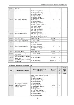
Page 16: ...mmand channel 0 Keyboard control 1 Terminal control 2 RS485 communication control 1 F0 03 Frequency given main channel selection 0 Keyboard no given 6 RS485communication port given 0 F0 04 Main channe...

Page 17: ...According to lower frequency operation 1 F0 14 ACC time 1 0 01 650 00s 6 0 F0 15 DEC time 1 0 01 650 00s 3 0 F0 17 Carrier frequency 0 6 15 0kHz 1 0 F0 18 Carrier frequency PWM characteristic selecti...

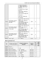
Page 18: ...0 00 60 00s Model setting F1 07 Stop method 0 DEC stop 1 Free stop 1 0 F1 08 DC braking start frequency when stopped 0 00 50 00Hz 3 50Hz F1 09 DC braking current when stopped 0 0 150 0 120 0 F1 10 DC...

Page 19: ...ion seclection 0 Invalid 1 Valid 0 F1 30 Power failure restart waiting time 0 00 120 00s 0 50s F1 31 Terminal operation protection selection LED 0 digit 0 Terminal operation command is invalid at powe...

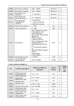
Page 20: ...terminal 7 X7 8 F2 07 Multifunction input terminal 8 X8 46 F2 09 X1 X4 input terminal filter time 0 000 60 000s 0 030s F2 11 X5 X8 input terminal filter time 0 000 60 000s 0 010s F2 29 Output terminal...

Page 21: ...al fault reset 1 Terminal fault reset and operation command 0000 F2 48 Brake invalid frequency threshold value 0 00 50 00Hz 1 00 F2 49 Brake invalid juding delay time 0 000 65 000s 0 100 F2 50 Band br...

Page 22: ...iption Range of setting and definition Factory default Pro per ty Com muni catio n add F3 00 VS1 lower value 0 00 10 00V 0 00V F3 01 VS1 lower limit setting 0 00 100 00 0 00 F3 02 VS1 upper value 0 00...

Page 23: ...ction 0 0 10V 1 4 00 20 00mA 2 0 00 20 00mA 3 FM frequency pulse output 0 F3 27 A02 input gain 25 0 200 0 100 0 F3 28 A02 simulationoutput signal bias 10 0 10 0 0 0 F3 29 A02FM frequency output lower...

Page 24: ...the second group LED 100 digit display the third group LED 1000 display the fourth group 3210 F4 14 The display content of the second line at the stop state LED 0 digit display the first group LED 10...

Page 25: ...nsor wire breakage detection 0 Wire breakage detection off 1 Wire breakage detection on LED 1000 digit PG feedback channel 0 PG interface 1 PUL interface 0001 F5 16 PG weekly pluse time 0 60000 1024 F...

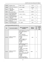
Page 26: ...ault and protection parameter set No Function description Range of setting and definition Factory default Pr op ert y Comm unicat ion add FA 00 Protection function selection 1 LED 0 digit ACC overcurr...

Page 27: ...cy stop and alarm 2 Limiting current and run LED 10 digit Input lack phase protection selection 0 Invalid 1 Valid LED 100 digit Output lack phase protection selection 0 Invalid 1 Lack phase detection...

Page 28: ...9 Acceleration and constant speed overvoltage suppression response gain 0 1 10 0 0 2 FA 20 Reserve FA 21 Motor overload protection coefficient 20 0 250 0 100 0 FA 22 Malfunction recovery times 0 5 0 F...

Page 29: ...tage 0 1500V FA 37 The last malfunction output current 0 1 2000 0A FA 38 The last malfunction bus voltage 0 3000V FA 39 The last malfunction module temperature 0 100 FA 40 The last malfunction inverte...

Page 30: ...10 00Hz FC 09 PLC multistage speed 10 0 00 320 00Hz 20 00Hz FC 10 PLC multistage speed 11 0 00 320 00Hz 30 00Hz FC 11 PLC multistage speed 12 0 00 320 00Hz 40 00Hz FC 12 PLC multistage speed 13 0 00...

Page 31: ...F9 04 Gate frequency Output frequency level 2 FDT2 0 00 50 00Hz 7 50 F9 05 X1terminal invalid delay time F1 07 is valid when freewheel stop is selected 0 10 000s 0 120 F9 06 X2 terminal invalid delay...

Page 32: ...ncy 0 00 100 00Hz 7 50 F9 19 Slewing acceleration deceleratio n time 2 determines the frequency 0 00 100 00Hz 50 00 F9 20 Slewing acceleration deceleratio n time 3 determines the frequency 0 00 100 00...

Page 33: ...ing torque 0 10000 400 FB 13 Frequency variation limit value 0 00 320 00Hz 3 00Hz FB 14 Reserved FB 15 Reserved FB 16 Oscillation suppression function selection 0 2 2 FB 17 Oscillation suppression pro...

Page 34: ...V C 05 Machinery speed 1RPM C 06 Setting torque 0 1 C 07 Output torque 0 1 C 08 Reserve C 09 Reserve C 10 Output power 0 1 C 11 Bus voltage 0 1V C 12 Module temperature 1 0 1 C 13 Module temperature 2...

Page 35: ...iagram X5 state X6 state X7 state X8 state X4 state X3 state X2 state input terminal off input terminal on X1 state Output terminal on off show diagram Reserved TA TB Y2 state output terminal off outp...

Page 36: ...er will restart automatically after FA 23 setting time External fault In certain application occasions external related equipments fault signals are considered in the inverter control system as usage...

Page 37: ...motor until it totally stops Set F1 00 as 1or 2 Reset V F curve or torque boost value Select inverter with right capacitance E oC2 Dec over curren t Deceleration time is too short Load potential energ...

Page 38: ...on parts are loose Fan is damaged Temperature detection circuit fault Make the environment meet the requirement Clear the air channel Check and reconnect the wire Change the same new fan Seek support...

Page 39: ...power open phase Check 3 phase output voltage and current Check wiring E HAL Current detection fault Detect circuit fault Phase imbalance Seek for technical support Check motor and wiring E EF Inverte...

Page 40: ...While disconnect output wire and run whether there is system fault alarm Three phase outout voltage balance is ok or not Whether overload or not Connect load and operate as follows Reduce load or enh...

Page 41: ...fault or misaction caused by noise Please find technic support Is deceleration time set too short Is acceleration time set too short Reduce the value Whether torque enhance value is too Can be reduce...

Page 42: ...n U V W and motor Stop motor and restart Or DC braking then start F1 00 1 Or speed track start F1 00 2 Whether it stops while restart the motor Whether act while load suddently changes to 0 Whether DC...

Page 43: ...ng or not Maybe inverter fault please seek for technic support Modify power supply system as required Adjust FA 10 setting Inner inverter over heat Inner inverter overheat E OH1 E OH2 Whether cooling...

Page 44: ...ctric thermal relay overload relay setting FA 20 is suiable Whether electric thermal relay overload characteristic matches the motor overload characteristic Inverter overload E OL2 Motor overload E OL...

Page 45: ...tion Whether keyboard Have input command signal or not It works after checking the cause and solving the problem Have input frequency signal or not It works after checking the cause and slving the pro...

Page 46: ...r the country are authorized by our company to provide warranty service Our company will only take on the liability return repair replacement according to our guarantee time and range If the user need...

Page 47: ......

Reviews: