AC80T Tower Crane Purpose VFD Manual
11
2.6 Standard connecting diagram
Note 2
Note 1
TA
TB
TC
+24V
Y1
GND
A01
V
W
U
M
~
Shield or armour cable (Grounding near
inverter side)
E
Grounding resistor <10
Ω
W
V
U
Output reactor
External brake resistor
Short circuit
P1
+
( )
+
10V
R
T
S
AC
input
VS2
GND
AS
VS1
PUL
Second speed
REW
FWD
External fault reset
COM
X7
X8
X3
X4
X6
X5
X1
X2
PLC
+24V
PB
( )
+
(-)
Inverter
S
T
R
GND
A02
Y2
COM
J1
J2
J3
Input reactor
Contactor
MCCB
Short circuit at factory
+
( )
Brake sticking output
Fault output
Third speed
Fourth speed
Fifth speed
Precautions:
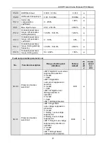
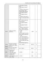
1. Multi-functional input terminal (X1~X8) can choose NPN or PNP transistor signal as the
input, the bias voltage can choose the inverter internal power supply (+24V terminal) or
external power supply (PLC terminal), factory value “+24V”and “PLC”are short
connected.
2. Analog monitoring output is for the specialized output of frequency meter, ammeter,
voltmeter, etc. Cannot be used for the control operations, like feedback control.
3. Due to the variety of pulse type in the actual use, the specific connecting mode should
refer to the detailed description.


