background image

The 

DSL Measurements

 mode and screen provides all the measurements related to the DSL layer and is displayed

automatically after achieving showtime. The BX100A/V synchronization process can be outlined as follows;

1. 

Activation, Discovery or Handshaking

 - Powering on the unit takes the DSL modem into activation and

acknowledgment phase, also known as handshaking. The goals of this phase are to determine which tones can be used and

how many bits can be assigned to each tone. Initialization typically uses two pilot tones to begin activation. Normally the

modem initiates the process when it is turned on and connected to the DSL line. Messages are sent using the pilot tones to

ensure that both ends are ready for transceiver training process.

2. 

Training

 - DSLAM measures and adjusts the power output to equalize the circuit. Unless configured otherwise, it

negotiates the fastest possible speed based on local loop conditions.

3. 

Channel Analysis

 - DSLAM tells the modem which options are configured and sends a predefined medley of tones so the

modem can report its signal-to-noise ratio.

4. 

Exchange

 - DSLAM sends the minimum signal-to-noise ratio and decides on the power output per tone.

5. 

Show Time

 - Initialization concludes in which the line is active and higher layer protocols such as ATM can begin

negotiation to transfer data over the connection.

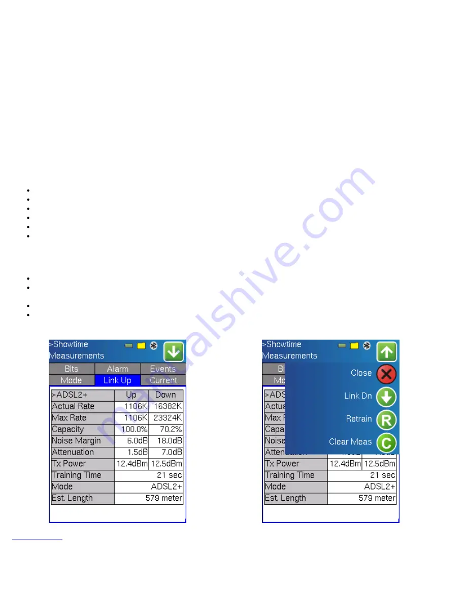
The following measurements and parameters are displayed in the various Tabs;

Link Up

 Tab: provides a snap shot of the link at initial turn up.

Current

 Tab: provides the current status of the link parameters and conditions.

SNR

 Tab (BX100A fitted with TI chipset): provides a tabular and graphical display of the Signal to Noise Ratio per tone.

Bits 

Tab: provides a tabular and graphical display of the bit allocation per tone.

Alarm

 Tab: provides information on any alarm occurring or having occurred on the line.

Events

 Tab: provides a log of all events that have occurred on the link since the test was started or measurement was

cleared or reset.

The Measurement Action Pull down menu performs the following functions;

Close:

 Closes the Pull Down Menu

Link Down/Link Up - 

a "Dying Gasp" signal, it sent to the DSLAM. The dying gasp message shows that the connection

went down because of loss of power and not because the cable was accidentally cut between the modem and DSLAM.

Retrain:

Clear Measurement:

 Resets the measurement counter.

BX100A Link-Up results

BX100V Measurement Action Menu

Go back to top

Link Up 

Tab: The initial showtime results are displayed. The screens may vary from BX100A to BX100V models, and from test

mode to test mode, however the result information maintains and retains the same basic definition/s.

BX100A/V e-Manual D07-00-001 Rev E01

Page 23 of 52

Summary of Contents for VePAL BX100A Series

Page 1: ...slated into a foreign language or be transmitted electronically without prior agreement and written consent of VeEX Incorporated as governed by International copyright laws Information contained in th...

Page 2: ...3 IP Overview 5 4 Pass Through Overview 5 5 Bitstogram Overview 5 6 Digital Multimeter Overview 6 0 DSL Measurement Setup 6 1 ADSL CPE ATU R mode ANSI G DMT G Lite ADSL2 ADSL2 Multi ADSL Multi G 992 x...

Page 3: ...o top 1 0 Product Introduction VeEX VePAL BX instruments are next generation test solutions to install and maintain xDSL networks delivering triple play services All BX products are lightweight rugged...

Page 4: ...1 1 Test Applications The diagram below outlines the major test capabilities of the BX100A V products BX100A V e Manual D07 00 001 Rev E01 Page 4 of 52...

Page 5: ...y for any errors or omissions In case of discrepancy the web version takes precedence over any printed literature c Copyright 2006 2010 VeEX Inc All rights reserved VeEX VePAL are registered trademark...

Page 6: ...our customer care department for customer support Before contacting our customer care department you must have your product serial number ready Please go to Basic Operations section for details on loc...

Page 7: ...ions Escape key The escape key provides an escape sequence to the user interface It is used in non touch screen operation mode to escape menus and functions Note Standby Mode By pressing Home and Help...

Page 8: ...tors and Panels Test Ports To access the test connectors please open the top cover DSL test port One RJ11 BX100V or one RJ45 BX100A connector is located at the top of the unit Connect the unit to the...

Page 9: ...the function key on the rubber keyboard O O The FRAME LED indicates synchronization aspects of the DSL signal The LED is green when showtime or link up is achieved The LED is red while the unit is tra...

Page 10: ...es information about the copper s performance but connection to the DSLAM or customer s modem can also be assessed The BX100A V models offer the following test functions depending on model purchased E...

Page 11: ...The destination address can be in IP address or URL format Trace Route To find the route to the destination IP or URL Often used to identify routing problems and unreachable destinations All the remo...

Page 12: ...te 4 3125 kHz wide bins called sub carriers Even though each of these 254 sub carriers or tones can support a modulation of up to 15 bits the maximum achievable downstream data rate is actually 8 128...

Page 13: ...DSL2 mode Also known as ITU T G 992 3 the standard extends basic ADSL data rates to 12 Mbit s downstream and 3 5 Mbit s upstream however actual speeds are dependent on line quality the most significan...

Page 14: ...y G 992 5 ADSL2 signal G 992 3 ADSL2 signal G 992 1 ADSL DMT signal G DMT ADSL signal ANSI T1 413 ADSL signal G Lite ADSL signal ADSL 2 Annex B Enables Annex B mode Screen layout differs slightly on B...

Page 15: ...is and ITU G 992 5 ADSL2 specification is that the upstream downstream frequency split has been shifted from 138kHz up to 276kHz allowing upstream bandwidth to be increased from 1 Mbit s to 3 5 Mbit s...

Page 16: ...ts the transmission of asymmetric and symmetric data rates up to 200 Mbit s The bandwidth can be extended to 30MHz however VDSL2 uses the same band plans below 12MHz to be spectrally compatible with V...

Page 17: ...nsmission Convergence PTM TC function that is based on the Ethernet in the First Mile EFM IEEE 802 3ah standard The PTM TC specified in VDSL2 makes provision for Preemption and Short Packet Support Pr...

Page 18: ...VDSL1 DSLAMs using DMT modulation VDSL2 CNXT Emulates Conexant based VDSL2 DSLAMs using DMT modulation VDSL IKO Emulates Ikanos based VDSL1 DSLAMs using DMT modulation VDSL2 IKO Emulates Ikanos based...

Page 19: ...and installations at customer premises often generate short bursts of noise of relatively high amplitude These bursts called impulse noise are electromagnetically coupled into the digital subscriber l...

Page 20: ...symbol duration can be corrected without errors One symbol equals 250 s therefore an INP of 1 correlates to a correction time of 250 s The Impulse Noise Protection INP or interleave depth is defined b...

Page 21: ...thers may be supported in future Annex A North America or B Europe Profile the following selections are available refer to VDSL2 profile and PSD limit tables below 8a B8 6 8b B8 6 12a B8 2 12a B8 6 17...

Page 22: ...numerous configuration profiles and bandplans to meet regional service provider requirements The frequency bandwidth has increased from 12 MHz to 30 MHz with options for 8 5 MHz 12 MHz 17 7 MHz and 3...

Page 23: ...gher layer protocols such as ATM can begin negotiation to transfer data over the connection The following measurements and parameters are displayed in the various Tabs Link Up Tab provides a snap shot...

Page 24: ...ommand to the time showtime is achieved Path Interleaved or Fast displayed on BX100A models only Mode This indication is particularly valuable when using the multimode setup Estimated Loop Length disp...

Page 25: ...with a SNR of 21 dB would be able to carry 7 bits However due to the fact that a minimum of 2 bits QAM 4 are encoded per bin the SNR of any single bin cannot drop below 6dB BX100V SNR Tone Graph BX10...

Page 26: ...Up to 15 bits per symbol can be encoded on each bin on a good quality line BX100A Bits Tone graph mode BX100V Bits Tone graph mode Each tone bin represents a 4 3125 kHz bandwidth and is used to transf...

Page 27: ...00V models due to xDSL chipset differences and capabilities BX100V Alarms BX100A Alarms Alarm definitions Line Performance parameter definitions FEC Up and Down Stream Count of near end Reed Solomon f...

Page 28: ...ved CRC 8 code word received does not match the code word transmitted A count of the superframes that contained CRC LCD Up and Down Stream Count of near end Loss of Cell Delineations for the interleav...

Page 29: ...ly in the relatively short list There are fewer Virtual Paths in the network than Virtual Channels so switches forward cells on the basis of the VPI Virtual Channel Identifier VCI As a cell approaches...

Page 30: ...lling the entire connection F4SG OAM F4 cell used for controlling a single segment of the connection Note Operation Administration and Maintenance OAM OAM performs standard loopback end to end or segm...

Page 31: ...values are displayed BX100A V OAM Statistics OAM Statistics tab displays information on the traffic received and transmitted Rate rate at which ATM cells are transmitted and received Count number of...

Page 32: ...p keypad Password enter information using pop up keypad Note LLC versus VC MUX encapsulation Virtual Channel Multiplexing VC Mux multiple VCs are created so that different protocols can be sent over e...

Page 33: ...lationship between peers using ATM Adaptation Layer 5 AAL5 for framing PPP encapsulated packets RFC2153 Point to Point Protocol provides a standard method for transporting multi protocol datagrams ove...

Page 34: ...mulate Customer Premise Equipment i e DSL modem After configuring both the WAN DSL and LAN Ethernet interfaces and establishing valid connections on each interface your PC will have connection to the...

Page 35: ...MUX available in LLC mode only Authentication PAP CHAP or Auto available in PPPoE and PPPoA modes only VPI Virtual Path Indicator Enter value in the range of 0 to 255 using the pop up keypad availabl...

Page 36: ...c host configuration protocol DHCP mode IP address Enter a value using the pop up keypad Subnet Network address to identify if the IP address falls within the local area network Scope start DHCP mode...

Page 37: ...ateway IP address of default gateway DNS IP Address of the Domain Name Server to be used by the tester Result Connection Passed or Failed Dynamic IP mode IP address Address of the network device or PC...

Page 38: ...nal or Loss of Synchronization condition since the start of the test Up Attenuation dB Upstream attenuation expressed in dB Difference in the power level transmitted at the near end modem and received...

Page 39: ...anomalies associated with the DSL link or line connection conditions Alarm types may vary from BX100A and BX100V models Pass Through Alarms CRC Count of the superframes that contained CRC FEC Count o...

Page 40: ...hich are included in unavailable time BlKES Count of the Block Error Rate LOSS Count of 1 second intervals containing one or more LOS defects of Sync Number of times the modem spontaneously retrained...

Page 41: ...deo packet carries a sequence number continuity errors can be determined easily Missing OOS and duplicate packets are counted as errors Packet loss is typically seen on all channels arriving at the cu...

Page 42: ...based on the data packet inter arrival time which is a measure of packet arrival variance Packet jitter affects packet arrival throughout the network Variations lead to buffer under overflows at the r...

Page 43: ...terval between the arrival of PCR values the accuracy of the expected values and also the jitter accumulated on those PCR values transmitted is necessary to assure that streams can be decoded PCR jitt...

Page 44: ...a Loss Rate e g 70 15 The above ratio shows a delay factor of 70ms and 15 packets lost per second MDI and MPEG packet loss together provides a good indication of IP transmission and non related IP iss...

Page 45: ...er being scanned Zap time ms Also known as inter channel change delay Time between a channel leave request is sent and the receipt of the first byte of data from the new multicast channel It is the IG...

Page 46: ...nents to the Network Quality of the Decoder from the Network Human Factors per unit time Go back to top 11 0 Bitstogram Measurement Mode The Bitstogram software option is available for both BX100A and...

Page 47: ...tabular format A zoom function allows fast and easy access to known tones BX100A V Bitstogram Graph Mode BX100A V Bitstogram Table Mode Bitstogram Events Tab Displays bit swapping associated with DMT...

Page 48: ...each end of the line Measurements can be obtained even when line conditions are so bad that a connection isn t even possible If a connection isn t possible the modem goes through each step of initial...

Page 49: ...p resistance tip ring with a short at the far end should not exceed 600 Ohms Capacitance a measurement will verify that a copper pair is balanced i e both the Tip and Ring leads are of equal length If...

Page 50: ...r elects to replace is returned to VeEX Inc by the customer along with proof of purchase within thirty 30 days of the request by the customer freight prepaid Additionally during the warranty period Ve...

Page 51: ...l health and safety requirements set out in European Directives To permit the use of a CE mark on a product proof that the item meets the relevant requirements must be documented Use of this logo impl...

Page 52: ...erification EXperts is an innovative designer and manufacturer of test and measurement solutions addressing numerous technologies Global presence through a worldwide distribution channel provides unco...

Reviews: