background image

Table of Contents

i

Introduction

Regulatory Agency Console Documentation  ....................................................................1
Related Manuals ...............................................................................................................1
Safety Symbols .................................................................................................................2

Site Considerations

Control Drawing  ................................................................................................................3
National Electrical Code Compliance ................................................................................4

Probe- to-Console Wiring .........................................................................................4
Probe Junction Boxes...............................................................................................4

Probe Wiring Safety Issues  ..............................................................................................5
Selecting a Console Location  ...........................................................................................5

Console Installation

Mounting the Console .......................................................................................................7
Wiring the Console  ...........................................................................................................9

Mag Probe Assembly

Attaching Probe Canister Spacer Rings  .........................................................................10
Assembling Floats onto Probe Shaft  ..............................................................................10
Attaching Cable Connector to Probe Canister ................................................................10

Probe Installation

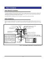
Probe Manhole Installation  .............................................................................................13
Probe Installation  ............................................................................................................13
Probe Conduit Installation ...............................................................................................14
Wiring Run Methods  .......................................................................................................15

Buried Rigid Conduit...............................................................................................15

Pulling Wires for Probes  .................................................................................................15

Direct Burial Cable..................................................................................................15

Sealing Field Connections  ..............................................................................................17

Wiring Run Through Rigid Conduit.........................................................................17
Direct Burial Cable..................................................................................................17

Connecting Probes to the Console  .................................................................................18
Probe Wiring Precautions  ...............................................................................................19

Input/Output Wiring Positions and Labeling ...........................................................19
Connecting Probes to the Console - Observe Polarity ...........................................19

Applying Power to System

TLS-HLD Cold Boot - Initial Power Up ............................................................................21
TLS-HLD Cold Boot - RAM Clear  ...................................................................................21
TLS-HLD Warm Boot ......................................................................................................21

RS-232 Communications

RS-232 Peripheral Equipment Requirements .................................................................22
RS-232 Connections .......................................................................................................22

To a Device Less Than 50 Feet from the Console .................................................22
To a Device More Than 50 Feet from the Console ................................................22

Surge Protection for Communication Devices  ................................................................23
Restricting System Programming Access .......................................................................24

Serial Security ........................................................................................................24
setup Security.........................................................................................................24

Summary of Contents for TLS-HLD

Page 1: ...Manual No 577013 784 Revision C Site Prep Manual TLS HLD...

Page 2: ...all components and units as soon as they are received If damaged write a complete and detailed description of the damage on the face of the freight bill The carrier s agent must verify the inspection...

Page 3: ...Installation 14 Wiring Run Methods 15 Buried Rigid Conduit 15 Pulling Wires for Probes 15 Direct Burial Cable 15 Sealing Field Connections 17 Wiring Run Through Rigid Conduit 17 Direct Burial Cable 17...

Page 4: ...n Code 902 40 Function Code A01 41 Function Code A02 42 Function Code A10 43 Function Code A11 44 Function Code A12 45 Troubleshooting Dual Function Front Panel Keys 46 Probe Diagnostic Menu 46 Probe...

Page 5: ...nstallation Example Above ground Storage Tank 14 Figure 9 Example Probe Wiring Run in Buried Rigid Conduit 15 Figure 10 Example Probe Wiring Run Via Direct Burial Cable 16 Figure 11 Probe Field Wiring...

Page 6: ...robe to console field junction box wiring diagram Attaching probe wiring to the console RS 232 serial communication connection requirements and serial commands Troubleshooting information that contain...

Page 7: ...s NO OPEN FLAMES Open flames from matches lighters welding torches etc can ignite fuels and their vapors NO POWER TOOLS Sparks from power tools such as drills can ignite fuels and their vapors USE SAF...

Page 8: ...e Wall Tank Single Wall Tank MP DP TLS 50 VEEDER ROOT Height Level Display TLS NOTE Intrinsically safe wiring marked shall be installed in accordance with Article 504 20 of the NEC ANSI NFPA 70 Note c...

Page 9: ...ns exceed 1000 feet Wire runs must be less than 1000 feet to meet intrinsic safety requirements Splices Veeder Root recommends that no splices be made in the wire run between a probe junction box and...

Page 10: ...type depth below grade sealing grounding wire capacities direct burial if permitted etc Selecting a Console Location Select a mounting location on the inside of any building The console must be prote...

Page 11: ...2 Installation Category II Consoles must be installed within the interior of buildings They are not suitable for any external location Ensure that the console is located where neither the console nor...

Page 12: ...or 240 Vac or a dedicated circuit breaker rated for 15 amperes 120 Vac or 240 Vac NOTE circuit breaker must be marked as the power disconnect for the console From an independent 24 hour supply at the...

Page 13: ...135 mm consoles tls50dimen eps 0 22 5 6 mm dia console mounting holes 4 places 3 75 95mm 0 4 10 mm 0 93 23 6 mm 0 93 24 mm 1 25 32 mm 0 93 23 6 mm 2 6 66 0 7 17 8 0 93 24 mm 6 7 170 mm 1 18 30 mm 1 2...

Page 14: ...s only 1 on top and bottom ref Figure 3 OFF 1 2 3 4 OPEN PROBE 6 PROBE 5 PROBE 4 PROBE 3 PROBE 2 PROBE 1 WARNING SUBSTITUTION OF COMPONENTS MAY IMPAIR INTRINSIC SAFETY NO REPAIRS SHOULD BE ATTEMPTED R...

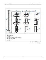
Page 15: ...ered and Boots from Probe Installation Kits are assembled on the probe shafts in the exact sequence and orientation shown in Figure 6 IMPORTANT Failure to push the boot as far as possible onto the pro...

Page 16: ...then slide ring over top of canister until tabs snap into groove in canister 2 Probe canister 3 After setting vanes see insert install bottom spacer ring Orient locking tabs as shown and then slide r...

Page 17: ...Legend for numbered boxes 1 Up 2 Bottom of probe shaft 3 4 Inch Floats 4 Product float slide on probe shaft first 5 Water float Optional slide on probe shaft second 6 Boot slide on probe shaft last 7...

Page 18: ...le Underground Storage Tank Riser cap with cord grip bushing and nut Concrete slab or packed earth per NFPA 80 Riser pipe 2 3 or 4 API schedule 40 depending on probe type To prevent erroneous probe re...

Page 19: ...compartment of the console see Figure 3 Use bushing and body of grip fitting supplied with probe and Adaptor nut supplied with AST kit Epoxy seal per NFPA specs Flexible metal conduit supplied with AS...

Page 20: ...Since wires for multiple probes may enter the console through a single conduit it is recommended that you use a different color code for each wire or individually mark each wire to identify probe inpu...

Page 21: ...thout proper precautions can result in fire explosion electrical shock hazardous conditions as well as equipment damage or inaccurate inventory control Perform the following 1 Use direct burial cable...

Page 22: ...CAUTION Epoxy sealant is irritating to eyes respiratory system and skin Can cause allergic skin reaction Contains epoxy resin and cycloaliphatic epoxycarboxylate Precautions Wear suitable protective c...

Page 23: ...console panel cover and connecting probe wires Do not short any voltage across any barrier terminal including probes consoles epxy2w eps To console Tie wrap Wire nuts From probe sensor or transducer...

Page 24: ...adhesive numbering labels furnished Accurately record on the circuit directory in Figure 13 the location of each probe as you attach wires to the probe input terminal block 2 IMPORTANT Once a device h...

Page 25: ...NTRINSIC SAFETY NO REPAIRS SHOULD BE ATTEMPTED REFER SERVICING TO QUALIFIED PERSONNEL ONLY AVERTISSEMENT LA SUBSTITUTION DE COMPOSANTS PEUT COMPROMETTRE LA SECURITE INTRINSEQUE Black wire from probe c...

Page 26: ...in the TLS HLD Setup manual to program the system TLS HLD Cold Boot RAM Clear If the system has previously been setup a cold boot can be initiated and the system reset such as for a software upgrade...

Page 27: ...e or both TO A DEVICE MORE THAN 50 FEET FROM THE CONSOLE If cable runs longer than 50 feet are needed two short haul modems should be used one at the console and one at the remote device We recommend...

Page 28: ...www bb elec com Telephone Line Surge Protector model TLSP RS 232 Surge Protector model 232DSP Computer Loopback Normal S2 DCE DTE S1 Black Box Model ME800A To Available Port Loopback Normal DCE DTE S...

Page 29: ...and diagnostic menus after initial programming Closing or turning on Switch position 4 inhibits use of the setup and diagnostic menus Figure 16 Console Dip Switch Settings DIP SWITCH SETTINGS In Figu...

Page 30: ...ter is done through a RS 232 serial port DB 9 connector on the bottom of the console Pin layout to connect the Console s Serial Interface DB 9 connector to a 25 pin computer terminal connector are sho...

Page 31: ...ge ext lang set page 33 601 Set Tank Configuration page 34 608 Set Tank Tilt page 35 881 Set Communication Port Data page 36 882 Initialize Communication Port Data page 37 883 Set Communication Port L...

Page 32: ...m Reset Version 1 Command Format Display SOH S00100 Computer SOH s00100 Typical Response Message Display Format SOH S00100 ETX Typical Response Message Computer Format SOH s001000000000000 CCCC ETX No...

Page 33: ...Alarm Reset Version 1 Command Format Display SOH S00300 Computer SOH s00300 Typical Response Message Display Format SOH S00300 ETX Typical Response Message Computer Format SOH s0030000000000 CCCC ETX...

Page 34: ...ge Computer Format SOH i201TT0000000000TT0ssssNNFFFFFFFF TTpssssNNFFFFFFFF CCCC ETX Notes 1 0000000000 Unused 2 TT Tank Number Decimal 00 all 3 0 Unused 4 ssss Tank Status Bits Bit 1 LSB Unused Bit 2...

Page 35: ...nse Message Computer Format SOH i205TT0000000000TTnnAA TTnnAA CCCC ETX Notes 1 0000000000 Unused 2 TT Tank Number Decimal 00 all 3 nn Number of alarms active for tank Hex 00 none 4 AA Active tank alar...

Page 36: ...aaaaaa Display SOH I50400 Computer SOH s50400aaaaaa Computer SOH i50400 Typical Response Message Display Format SOH I50400 aaaaaa ETX Typical Response Message Computer Format SOH i504000000000000aaaaa...

Page 37: ...Inquire Display SOH S50C00f Display SOH I50C00 Computer SOH s50C00f Computer SOH i50C00 Typical Response Message Display Format SOH I50C00 f ETX Typical Response Message Computer Format SOH i50C000000...

Page 38: ...al Response Message Display Format SOH I51700 U LL ETX Typical Response Message Computer Format SOH i517000000000000ULL CCCC ETX Notes 1 0000000000 Not Used 2 U System Units 1 U S 2 Metric 3 LL System...

Page 39: ...TTf Display SOH I601TT Computer SOH s601TTf Computer SOH i601TT Typical Response Message Display Format SOH I601TT f ETX Typical Response Message Computer Format SOH i601TT0000000000TTf TTf CCCC ETX N...

Page 40: ...otes 1 TT Tank Number Decimal 00 all 2 HHH HH Tank Tilt Decimal 3 FFFFFFFF Tank Tilt ASCII Hex IEEE float Typical Response Message Display Format SOH I608TT TT HHH HH ETX Typical Response Message Comp...

Page 41: ...al Response Message Display Format SOH I881CC CC BBBBB P S D T AA ETX Typical Response Message Computer Format SOH i881CC0000000000CCBBBBBPSD0AA CCCC ETX Notes 1 0000000000 Not Used 2 CC Communication...

Page 42: ...sent to confirm the command Typical Response Message Display Format SOH I882CC CC BBBBB P S D T AA ETX Typical Response Message Computer Format SOH i882CC0000000000CCBBBBBPSD0AA CCCC ETX Notes 1 00000...

Page 43: ...H s88300LL Computer SOH i88300 Typical Response Message Display Format SOH I88300 LL ETX Typical Response Message Computer Format SOH i883000000000000LL CCCC ETX Notes 1 0000000000 Not Used 2 LL Syste...

Page 44: ...y SOH S88400f Display SOH I88400 Computer SOH s88400f Computer SOH i88400 Typical Response Message Display Format SOH I88400 f ETX Typical Response Message Computer Format SOH i884000000000000f CCCC E...

Page 45: ...49787 vvv rrr B CREATED YY MM DD HH mm ETX Typical Response Message Computer Format SOH i902000000000000SOFTWARE 347871 vvv rrrCREATED YY MM DD HH mm CCCC ETX Notes 1 0000000000 Not Used 2 vvv Softwar...

Page 46: ...AG1 3 LLLL LL Probe Length Decimal 4 SSSSSS Probe Serial Number Decimal 5 cccc Probe Date Code Hex Typical Response Message Computer Format SOH iA01TT0000000000TT0PPKKKKFFFFFFFFSSSSSScccc TT0PPKKKKFFF...

Page 47: ...es 1 TT Tank Number Decimal 00 all 2 PP Probe Type 03 MAG1 3 CCC CCCC Probe Data Decimal Typical Response Message Computer Format SOH iA02TT0000000000TT0PPNNFFFFFFFF TT0PPNNFFFFFFFF CCCC ETX Notes 1 0...

Page 48: ...ss ssss sss ssss sss ssss sss ssss sss ssss sss ssss sss ssss sss ssss sss ETX Notes 1 TT Tank Number Decimal 00 all 2 PP Probe Type 03 MAG1 3 nnnnn Sample Number Decimal 4 ssss sss Probe Data Decimal...

Page 49: ...s ssss sss ssss sss ssss sss ssss sss ssss sss ssss sss ssss sss ssss sss ETX Notes 1 TT Tank Number Decimal 00 all 2 PP Probe Type 03 MAG1 3 nnnnn Sample Number Decimal 4 ssss sss Probe Data Decimal...

Page 50: ...ss ssss sss ssss sss ssss sss ssss sss ssss sss ssss sss ssss sss ssss sss ETX Notes 1 TT Tank Number Decimal 00 all 2 PP Probe Type 03 MAG1 3 nnnnn Sample Number Decimal 4 ssss sss Probe Data Decimal...

Page 51: ...period longer than 2 seconds will change the system language to the next available language queued in software Repeat this procedure until the desired language is displayed Pressing the Back key down...

Page 52: ...Serial Number XXXXX Serial number of the probe T1 Probe ID XXXXX Manufacturing code of the probe T1 Probe Length XXX Length of the probe T1 Gradient XXX XXXX Probe calibration factor used to calculat...

Page 53: ...4 xxxxx xxxxx xxxxx 05 xxxxx xxxxx xxxxx 06 xxxxx xxxxx xxxxx 07 xxxxx xxxxx xxxxx 08 xxxxx xxxxx xxxxx 09 xxxxx xxxxx xxxxx 10 xxxxx xxxxx xxxxx 11 xxxxx xxxxx xxxxx 12 xxxxx xxxxx xxxxx 13 xxxxx xxx...

Page 54: ...r The CPU board is removed by inserting a straight slot screwdriver into one of the two indents on the bottom of the board and then gently prying against the door until the board clears the upper dete...

Page 55: ...3 Attach anti static strap to your wrist and to a good ground 4 Disconnect the CPU board cable from the Power Supply board Remove the CPU board following the instructions in Replacing the CPU Board on...

Page 56: ...r equivalent Chip socket Removable chip Chip removal slots Lift up chip when it is free from socket Chip socket consoles h8remov1 eps Chip socket Incorrect Angle Correct Angle INCORRECT ANGLE CORRECT...

Page 57: ...ssed in the socket s base or 2 If the chip is covered with a label you can also orient the chip correctly if you insert the chip in the socket with its angled corner in the same angled corner of the s...

Page 58: ...op Level Menu Product Height Product Temperature requires probes that have temperature measurement capability Water Height requires probes that have water measurement capability Pressing the Tank key...

Page 59: ...arm Index Cause and Corrective Action Alarm Cause Action PROBE OUT If the console is not reliably communicating with the probe the Probe Out alarm will acti vate Call for service following the procedu...

Page 60: ...tage 120 240 Vac 2 A max The Power Supply board fuses F1 and F2 are NOT field replaceable The rating for both fuses is 2 A Type T Time Lag SIGNAL INPUT SPECIFICATIONS Up to 6 probes monitored with TLS...

Page 61: ...0 75 C001 Std 2 float Red Yes 9 5 0 75 D000 Std Inv only 2 flt Green Yes 9 5 0 75 D001 Alt 1 float Black No 7 D002 Alt 1 float Red No 7 D003 Alt Inv only Green No 7 Mag Probes Form Numbers 8463 8493...

Page 62: ...For technical support sales or other assistance please visit www veeder com...

Reviews: