


3
Site Considerations
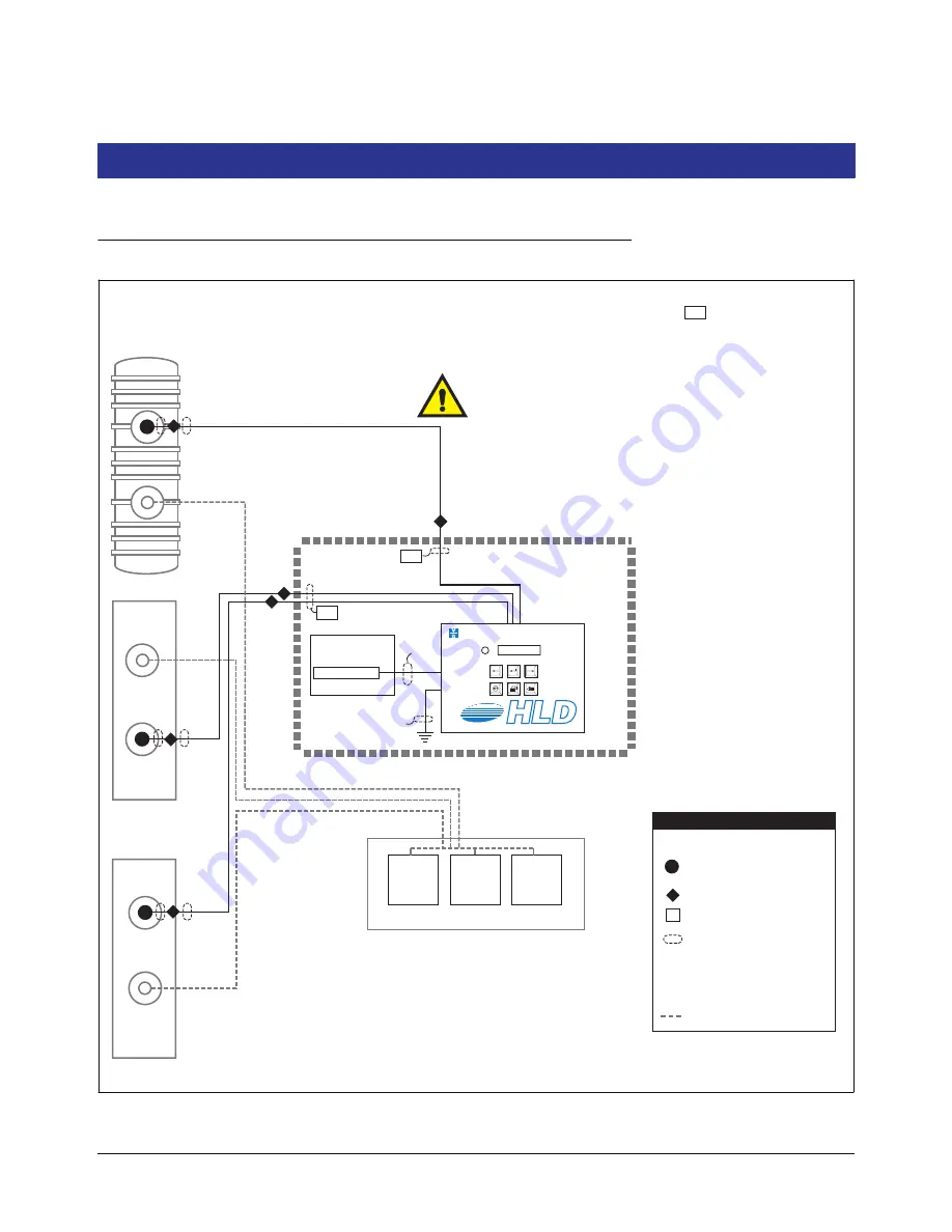
Control Drawing
Figure 1. Control Drawing - Example TLS-HLD System Site Layout
MP
MP
Non-Hazardous
Area
Circuit breaker panel
or Fused, switched,
neon indication spur
120 or 240 Vac
12 AWG barrier
ground wire
MP
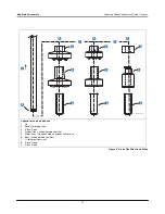
Magnetostrictive Probe
consoles\hldsysdia.eps
Hazardous
Area
DISPENSERS
Hazardous Area
Expoxy Sealed Connection in
a Weatherproof Junction Box
Seal-Off
LEGEND
1/2'' (12.7 mm) Rigid Conduit
Terminal Connection
PA
Conduit Enters Console in an
Intrinsically Safe Area Knockout
Conduit Enters Console in a
Power Area Knockout
IS
PA
Product piping
Double Wall Tank
Single Wall Tank
Single Wall Tank
MP
DP
TLS-50
VEEDER-ROOT
Height Level Display
TLS
NOTE: Intrinsically safe wiring (marked ) shall be installed in
accordance with Article 504-20 of the NEC, ANSI/NFPA 70.
Note: conduit requirements are dependent on local electrical regulations.
For probe-to-console wiring, shielded cable is required regardless of
conduit requirements.
WARNING:
Substitution of components may impair intrinsic safety.
Circuitry within the TLS-HLD Console barrier forms an intrinsically safe,
energy-limited system. This system makes TLS-HLD probes safe for use
in a Class I, Group D hazardous location. TLS-HLD probe wiring is
intrinsically safe only when connected to Veeder-Root's TLS-HLD
Console. Reference Console Form Number 8469 and Probe Form
Numbers 8462, 8463, 8468, and 8473.
I.S.
I.S.
I.S.


