13
Probe Installation
Probe Manhole Installation
At each underground probe location, install a 14-inch (355 mm) minimum diameter approved manhole according to the
manufacturer’s instructions (Note: probes should be located at least 24 inches (610 mm) from the submersible pump to
avoid erroneous probe readings when the pump is running).
Position the manhole so that there is necessary clearance for junction box installation and wiring.
Probe Installation
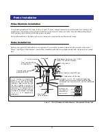
Each probe supplied by Veeder-Root is accompanied by an assembly manual which details the assembly of the probe.
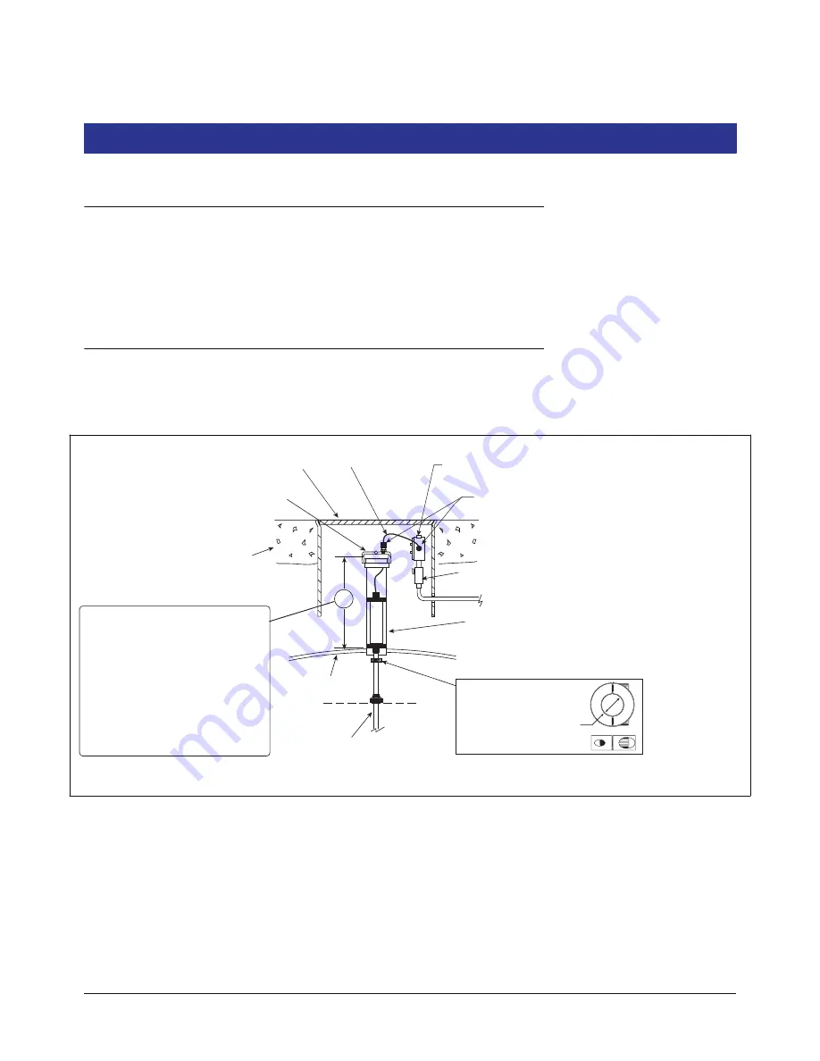
Figure 7 and Figure 8 illustrate how to install the assembled probe either in an underground tank, and in an above ground
tank.
Figure 7. TLS-HLD Probe Installation Example - Underground Storage Tank
.
.
.
.
.
.
.
.
.
.
.
.
.
.
.
.
.
.
.
.
.
.
.
.
.
.
.
.
Riser cap with cord grip
bushing and nut
Concrete slab or packed
earth per NFPA 80
Riser pipe - 2, 3, or 4'' API schedule 40 depending
on probe type (To prevent erroneous probe readings,
install probe riser a minimum of 24'' from the submersible
pump.)
Cord grip seals
Weatherproof junction box with 1/2" NPT
threads (16 cubic inch minimum)
14'' min. dia. manhole
Seal-off, epoxy seal per NFPA spec
Mag Probe
(rests on bottom)
Tank
A = 18" minimum for standard mag
probes or 14" minimum for global
mag plus/mag plus probes. When
installing a probe longer than the
the tank diameter, increase this
minimum dimension to compensate.
(Example: a 7'-6'' diameter tank will
use an 8' probe, in which case you
must add 6" to minimum riser length
'A', i.e., 24" or 18" depending on
probe type).
probes\pbinstcen.eps
1/2" Rigid conduit (to Console)
Probe cable
A
Split-Ring Collar
(P/N 576008-617)
required if probe
enters the riser.
Top view
Side view
3/4" ID


