


26
UM001
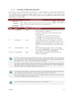
The minimum value of zero turns off all adaptive tuning.
The maximum value of 10 applies several times the estimated level of uncertainty.
Adaptive Filtering Gain
The adaptive filtering stage of the VPE monitors both the magnetic and acceleration measurements to
determine if large amplitude high frequency disturbances are present. If so then a variable level of filtering
is applied to the inputs in order to reduce the amplitude of the disturbance down to acceptable levels
prior to inputting the measurement into the attitude filter. The advantage of the adaptive filtering is that
it can improve accuracy and eliminate jitter in the output attitude when large amplitude AC disturbances
are present. The disadvantage to filtering is that it will inherently add some delay to the input
measurement. The adaptive filtering gain adjusts the maximum allowed AC disturbance amplitude for the
measurement prior to entering the attitude filter. The larger the allowed disturbance, the less filtering
that will be applied. The smaller the allowed disturbance, the more filtering will be applied.
This parameter can be adjusted from 0 to 10.
The minimum value of zero turns off all adaptive filtering.
The maximum value of 10 will apply maximum filtering.
Keep in mind that regardless of this setting, the adaptive filtering stage will apply only the minimal amount
of filtering necessary to get the job done. As such this parameter provides you with the ability to set the
maximum amount of delay that you are willing to accept in the input measurement.
3.5
Communication Interface
The VN-100 provides two separate communication interfaces on two separate serial ports.
3.5.1
Serial Interface
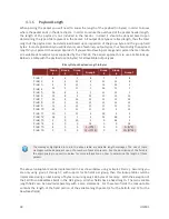
The serial interface consists of two physically separate bi-directional UARTs. Each UART supports baud
rates from 9600 bps up to a maximum of 921600 bps.
The rugged version includes an onboard TTL to RS-232 level shifter, thus at the 10-pin connector one serial
port is offered with RS-232 voltages levels (Serial 1), while the other serial port (Serial 2) remains at 3V
TTL logic levels.
It is important to note that the ability to update the firmware using the onboard bootloader is only
supported on the serial port 1 interface. It is highly recommended that if serial port 1 is not used for
normal operation, a means of accessing it is designed into the product to support future firmware
updates.
3.5.2
SPI Interface
The SPI interface consists of a standard 4-wire synchronous serial data link which is capable of high data
rates up to 16 Mbps. The VN-100 operates as slave on the bus enabled by the master using the slave
select (SPI_CS) line. See the Basic Communication chapter for more information on the operation of the
SPI interface.


