Page 2 / 16
Installation Steps
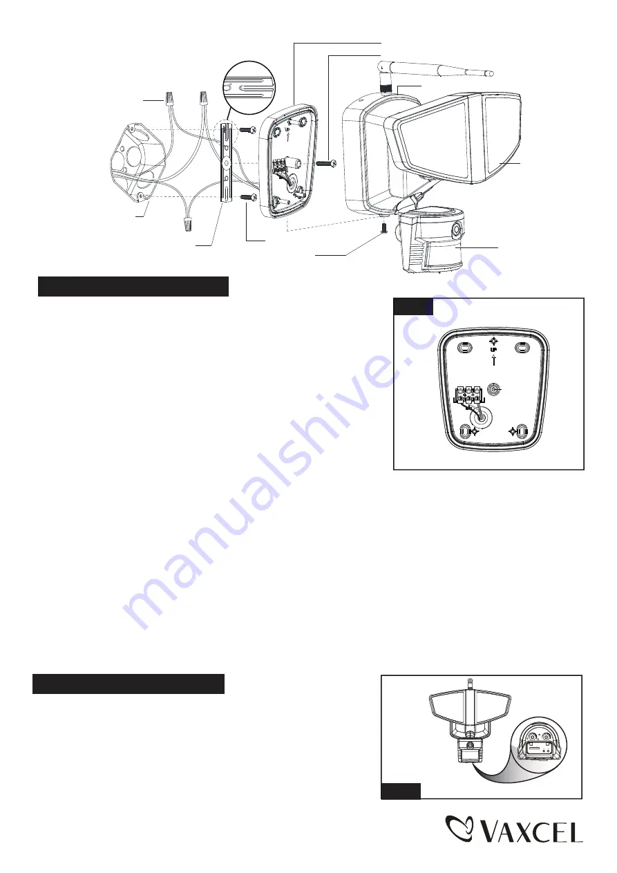
1. The fixture mounting bracket is pre-assembled on the light fixture.
Unscrew the fixture mounting screw in order to remove the mounting
bracket.
2. Install the mounting strap to the outlet box with the stamped word
“FRONT” facing away from the outlet box, using two mounting
screws that best fit the outlet box. Mounting bracket should sit
flush against wall surface when secured.(Choose one matching
pair of suitable mounting screws from the 3 pairs provided)
3. Pull out the source wires from the outlet box. Make wire connections
using wire nuts as follows:
---Connect the black wire from the fixture to the “hot” wire from the
power source. (usually black)
---Connect the white wire from the fixture to the neutral wire from the
power source. (usually white)
---Connect the grounding wire from the fixture to the grounding wire
from the power source. (usually green / yellow insulation)
Carefully tuck the wires back into the outlet box.
4. Place mounting bracket against the outlet box, insert the mounting bracket screw through the mounting bracket hole,
thread mounting bracket screw into the center hole of the mounting strap. Tighten the mounting bracket screw securely.
▲ When mounting to a wall, the “UP” arrow must point upward. (See Fig. 1)
▲ When mounting to an eave, the “UP” arrow must point toward the building.
5. Attach the back plate of the light fixture to the mounting bracket, secure it with the fixture mounting screw.
6. With silicone caulking compound, caulk completely around where the mounting bracket meets the wall surface.
CAUTION: Be sure to caulk completely where the mounting bracket meets the wall surface to prevent water
from seeping into the outlet box.
Sensor
Mounting Strap
Mounting Bracket
Outlet Box
Wire Nut
Back Plate
Mounting Screw
Light Head
-- Rotate the motion sensor so the controls face toward the ground.
Adjusting the Sensor Head:
Turn off the power at fuse or circuit box.
Turn on the power at fuse or circuit box.
Fig. 2
Fixture Mounting Screw
Mounting Bracket Screw
Fig. 1
FRONT
L
(B
la
ck
)
N(White)
L
(
B
la
c
k
)
N(White)
SD
RESET WPS
5s
10Min
TIME
LUX
150616


