40
03-914647-00:4
The following instructions are for instruments configured with manual
pneumatics. Gas flows for detectors with EFC are set in the Adjustments
Section of the detector method.
Follow the steps below to set all gas flow rates on the 3800 Gas
Chromatograph. Flows are typically set with carrier gas first followed by
make-up and detector fuel gases. The most convenient way to measure or
verify gas flows is at the detector exit. Adapters are provided in the individual
detector accessory kits for this purpose.
1
Attach a bubble or digital flowmeter to the detector outlet using the
appropriate adapter.
2
Turn off make-up and detector gases at the pneumatics panel. For
a needle valve this is accomplished by turning the needle valve
cartridge knob fully clockwise. For a flow controller this is
accomplished by turning the flow controller knob fully counter-
clockwise or until the turns counting dial reads zero.
3
Observe reading on flowmeter. Ensure it is within the range
described in the table for carrier gas flow rates.
4
Adjust the carrier gas flow using the manual pneumatics controls on
the pneumatics panel or by adjusting the Electronic Flow Control to
achieve the desired flow rate.
5
For a capillary system, turn on the make-up needle valve and adjust
to achieve the desired flow rate. The combined carrier and make-up
flow should be 30 mL/min. Adjustment is done with a small flat
screwdriver inside the needle valve cartridge knob.
6
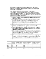
Turn on the relevant detector fuel gases in the sequence hydrogen
followed by air. Use the table below to calculate the combined flows
for the specific detector. For the TSD adjust the hydrogen flow
controller until the turns dial reads 400.
Detector
C
make-up
C make-
up + hydrogen
C make-up +
hy air1
C make-up +
hyair1 +
air2
FID
30
60
360
TSD
30
34
209
PFPD
2
15
32
42

