background image

8

Technical Support: [email protected] US: +866 677 0053 EU: +44 (0) 1793 230 343

using Cat5e as standard, we suggest using Cat6 as 

the preferred cable due to its improved transmission 

capabilities.

If using a Duplicate display mirrored to the HDBT Output,

connect the display via the HDMI OUT port.

ATTENTION

 We strongly recommend using the

supplied mounting brackets to secure the MATRIX

and the accompanying TRANSMITTER & DISPLAY

RECEIVER baluns. Any sudden movement of these 

devices could lead to loss of picture and sound if

connections become loose or strained, resulting in

unnecessary service call backs.

        Connect the HDMI OUT of the DISPLAY RECEIVER 

to the HDMI IN of the display.

         Plug the 3.5mm jack of the IR RX receiver into the 

IR RX port of the display receiver balun. Place the IR RX 

receiver sensor discretely on the front of the display with 

care taken to achieve a clear line of sight with the remote 

control to be used.

For two-way IR controlling the display from the matrix 

end: Plug the 3.5mm jack of the IR TX emitter into the 

corresponding IR TX port on the display receiver, ensuring 

the emitter is placed directly over the infra-red receiving 

sensor of the display using the adhesive backing.

Again, adjustment of receiver and emitter position may be 

needed to achieve the best IR signal distribution.

        After ensuring the display receiver 

balun is fixed firmly in place behind the 

display, insert the 5v mains power adaptor 

(included) or connect the USB to 5v 

power cable.

        Switch on the power to your input sources, displays, 

and any display receivers used.

Finally, switch on the matrix at the rear and your 

Wyrestorm system should now be fully connected and 

ready for use.

ATTENTION 

Remember, always switch off the matrix 

before unplugging any inputs or outputs – follow 

last on, first off protocol. 

If your IR emitters and receivers are correctly placed you 

should now be able control both sources and displays 

discretely from either location.

ATTENTION 

If there is electrical interference or 

cable bends/kinks within the set up the IR is one of 

the first functions to fail.

If you do not have IR control:

• Check your cables are straight with jacks firmly

connected to ports.

• Check your IR sensors are unobstructed and able to

receive infrared signals.

• Check direct sunlight on the emitters/receivers is not

affecting the infrared signal.

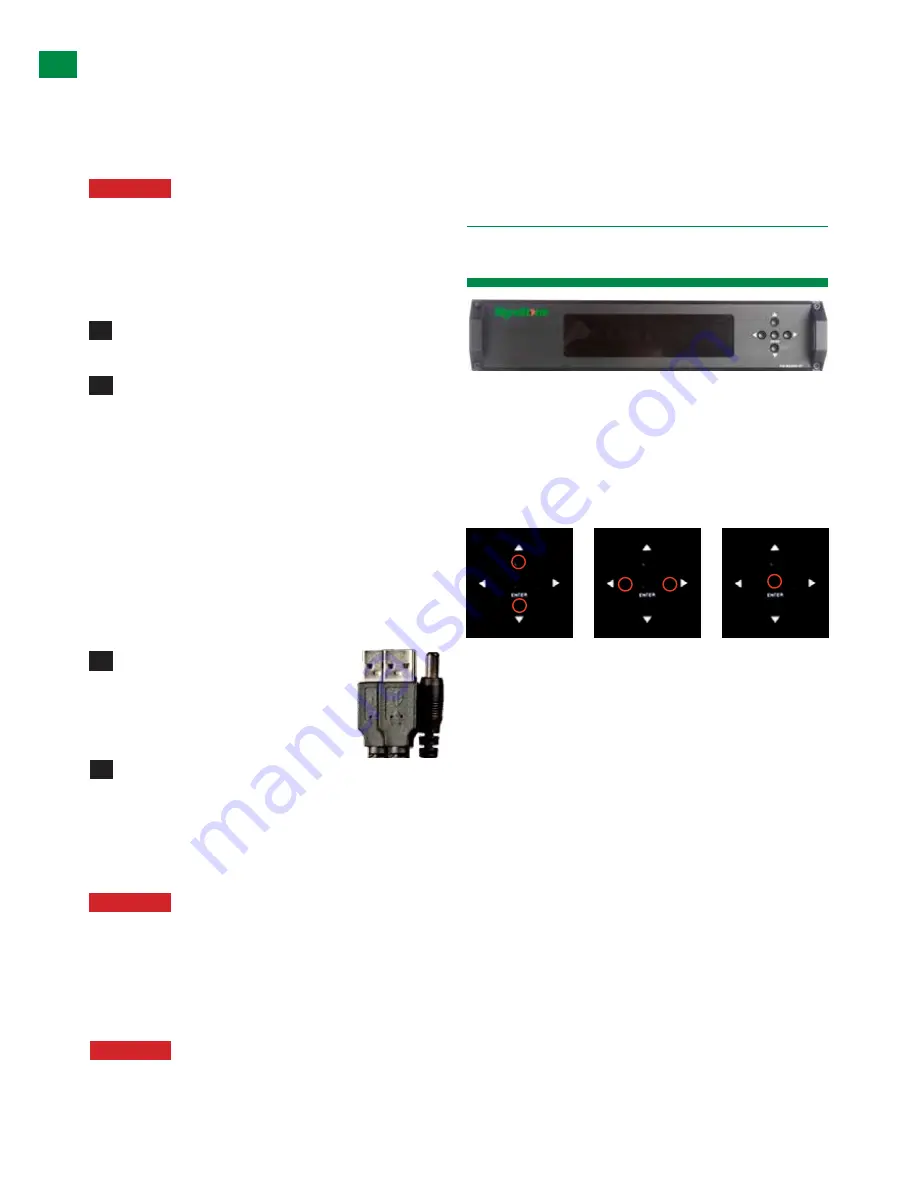
The Wyrestorm MX0606/0808-PP is designed with ease 

of set-up and use in mind. Basic switching of source 

inputs to output displays can be achieved via the front 

panel control of the matrix.

On power up, the front panel will flash as the matrix 

initialises. When the display stops flashing, the matrix is 

ready to use.

OUTPUT selection      INPUT selection                  Confirm  


             OUTPUTS/INPUTS

OUTPUTS are selected by pressing the LEFT and 

RIGHT arrow buttons to scroll forwards and backwards 

numerically through the displays connected to the matrix. 

The corresponding OUTPUT channel number will blink on 

the display when reached.

Likewise, the UP and DOWN arrow buttons scroll 

numerically through any INPUT sources connected to 

the system. When the desired OUTPUT and INPUT is 

reached, push the ENTER button to confirm the selection. 

The display will stop blinking to let you know the matrix 

has been set.

Repeated pressing of the select button of a specific 

output scrolls numerically through the HDMI input devices 

connected to the matrix, with the corresponding LEDs 

illustrating when a device has been selected for that 

particular output. The chosen input will automatically 

store for the output so, even when the matrix is powered 

off and on, the last selected input/output combination will 

remain. 

5

7

6

8

10.     Basic Operation

TYPICAL APPLICA

TION, BASIC OPERA

TION

Summary of Contents for HDBaseT Lite

Page 1: ...osing this product Please read these instructions carefully before installing to avoid complications later Vanco Powered by WyreStorm 8x8 HDBaseT Lite Matrix Part Number VPW 280771 8 Input 8 Output single cable matrix with 2 way IR control ...

Page 2: ...ch as Coax Fibre or full HDBaseT for unrivalled choice and compatibility The system offers flexibility and reliability of signal distribution combined with innovative features and an ease of use to deliver HD audio and video controlled via IR RS232 or LAN all on a single Cat5e 6 7 cable that removes the need for additional control and video cables on installations whether in a residential or comme...

Page 3: ...n servicable parts Refer all servicing to qualified service personnel WARNING To reduce the risk of fire electric shock or product damage 4 Technical Support support wyrestorm com US 866 677 0053 EU 44 0 1793 230 343 FEATURE Each Output port can be fed to multiple displays cascaded Enables up to 4 HDMI video audio devices to be independently switched through up to 4 HDMI displays or projectors for...

Page 4: ... x stylus 5 Specifications Output Video HDMI v1 4 with full 3D com patibility with Frame Sequen tial Blu ray and Interlaced Stereoscoptic satellite cable broadcasts Audio Format Supported DTS HD Dolby True HD Max Transmission distance over HDMI 15m 49ft if a longer HDMI connection is necessary we offer the Wyrestorm in line HDMI to HDMI coupler RP HD HD Max Transmission distance over Cat5e 6 7 70m...

Page 5: ... IR RX HDMI OUT HDBT OUT HDMI IN IR RX HDMI OUT HDBT OUT HDMI IN IR RX HDMI OUT HDBT OUT HDMI IN IR TX 123456 RS485 RS232 LAN IR RX HDMI OUT HDBT OUT HDMI IN IR RX HDMI OUT HDBT OUT HDMI IN 1 2 3GROUP4 5 6 RJ45 RS285 DEFINITION RJ45 PIN 1 2 7 8 DESCRIPTION TX TX RX RX DEFAULT 1 1 0 ON OFF 23 4 5 7 6 8 9 12 1 4 10 13 15 2 11 14 16 3 LED Input Output Select Screen HDBT Output ports RJ45 Cat5e 6 7 IR...

Page 6: ... Mirror of 08 70m 230ft 49ft 32ft 16ft 65ft 82ft 98ft 114ft 131ft 147ft 164ft 196ft 229ft 262ft 15m 10m 5m 20m 25m 30m 35m 40m 45m 50m 60m 70m 80m 1080p 1080i HDBaseT Lite range 1080p MX0606 PP MX0808 PP with RX 1UTP IR70 display receiver Cat 5e 6 cable performance Cat 5e 6 wiring guide The quality of termination for every RJ45 is essential Poor termination leads to intermittent performance and lo...

Page 7: ...re pushed securely into each port and supported by the connector strain relief clip to prevent them from becoming loose The quality of termination for your RJ45 is essential Poor quality terminations lead to intermittent performance and longer install times HINT Although all Wyrestorm products are tested using Cat5e as standard we suggest using Cat6 as the preferred cable due to its improved distr...

Page 8: ...nplugging any inputs or outputs follow last on first off protocol If your IR emitters and receivers are correctly placed you should now be able control both sources and displays discretely from either location ATTENTION If there is electrical interference or cable bends kinks within the set up the IR is one of the first functions to fail If you do not have IR control Check your cables are straight...

Page 9: ...ontrolling the matrix remotely from the display side th matrix automatically detects which particular output location the user is at and only allows the selection of sources 1 8 fo that particular location using the button the right han button will be deactivated For example if you are in the Master Bedroom with a display connected to output 3 of the matrix the output zone is automatically detecte...

Page 10: ...e 6 7 cable The sequence of IR TX numbers correspond to the HDMI INPUTS so when an OUTPUT selects a certain INPUT the CALL BACK IR signal of that RJ45 port selects the relevant IR TX port to OUTPUT the control signal Example If OUTPUT 1 selects INPUT 3 the CALL BACK IR signal of that RJ45 OUTPUT links INPUT 3 with IR TX3 for the signal to be combined and communicated for that input to be controlle...

Page 11: ...CED OPERATION 02 At display end Insert the IR RX Receiver jack into the IR RX port of the display receiver balun with the receivers themselves placed in clear view on or near the displays to receive an infrared signal from the remote handset used to control inputs Insert the IR TX Emitter jack into the IR TX port of the display receiver balun ensuring that the emitter sensor is securely attached t...

Page 12: ...system for third party control RS232 Remote Control Control of the matrix is possible through RS232 using third party control systems or the dedicated Wyrestorm COM CTL software included with your purchase also downloadable from www wyrestorm com RS232 Setting Should third party control be required please see below for control system configuration and hex code input The RS232 connection on the mat...

Page 13: ... is connected or disconnected to the Com Port and communication is enabled Selection between ports is available by pressing the Com Port Select button 07 When connected the only option will be to Disconnect and vice versa Press to connect disconnect the matrix from the software control Connected to ENABLE matrix communication Disconnected to DISABLE matrix communication Com Select Connect Disconne...

Page 14: ...elections by allocating your choices to Save buttons 1 3 and recall previously saved output input configurations by pressing State 1 3 buttons Firmware Update To update the system firmware enter the following code into the Send Message Window ensuring to include one space between each section of the code Code 1CP BE 7C 5F Press Enter then Send Message to put the matrix into firmware update mode Pr...

Page 15: ...ess information necessary for LAN control 14 01 02 03 04 Clicking opens a pop up window in which you can choose to let the system automatically detect your IP address with the result displayed in the box below Alternatively if the system cannot detect an IP address select Use the following IP Address and you can add manually 01 Selection enables the IP address to be obtained automatically with the...

Page 16: ...l appear in the central section 2 Use your cursor to click into the box containing the IR data you wish to change 3 With the remote control pointing at the device press the handset button you wish to transfer IR Code from and the code will appear in your selected IR Code box 4 To confirm this change click to save the changes to the system 5 Hit to close the IR Code Setting window and the device wi...

Page 17: ... Matrix via ode Third t is rom the y code be edited if ol systems stom code om codes vice to n code If petition of de nd Control r the is ode de of 63 69 next Input 06 8 07 16 8 07 26 8 27 36 8 37 46 8 47 56 8 57 66 8 67 If the control command is sent successfully the current output state selected will feedback to show the in put port selected The return status format is as follows S X1 X2 r n Thi...

Page 18: ...s and MAC address of the MX0606 0808 PP as well as its name if you decide to change the name of your matrix see Device Name section below On subsequent openings NETCTL will then search the Matrix for the saved data required for connection If using for the first time the program will automatically detect the IP address being used with the result displayed in the white area beneath Should no result ...

Page 19: ... detect the IP address being used with the result displayed in the white area beneath Should no result appear or if the system is unable to detect an IP address automatically press the button to locate When the IP address appears click to attach the IP address to the system and the IP address will change to a default factory serial number MX0606 PP or MX0606_HE1 MX0808 PP or MX0808_HE1 Device Name...

Page 20: ...put eft hand 1 4 can be s into the ws Click to assign the new IP address to the system and you will return to the previous screen or to return without changes taking effect Now click for the Matrix to detect the new IP address which will appear in the dialog box Finally click to confirm IP settings ATTENTION This Assign IP process differs from the COM CTL IP Set function Set IP in COMCTL saves rea...

Page 21: ...munication Remaining settings no function reserved for future updates 1 2 3 4 ON 1 2 3 4 ON 1 2 3 4 ON 1 2 3 4 ON 1 2 3 4 ON 1 2 3 4 ON 1 2 3 4 ON 1 2 3 4 ON 1 2 3 4 ON 2 3 4 ON 1 2 3 4 ON 1 2 3 4 ON 1 2 3 4 ON 1 2 3 4 ON 1 2 3 4 ON 1 2 3 4 ON 1 2 3 4 ON 1 2 3 4 ON 1 2 3 4 ON 1 2 3 4 ON 1 1 2 3 4 DEFAULT ON OFF 2 3 4 ON 1 2 3 4 ON 1 2 3 4 ON 1 2 3 4 ON 1 2 3 4 ON 1 2 3 4 ON 1 2 3 4 ON 1 2 3 4 ON 1...

Page 22: ...reduced transmission that may manifest itself in poor picture quality or a complete lack of picture 5 Signal Reduction Are you using stranded patch leads as interconnects between patch panels or wall outlets Such use reduces signal strength we recommend solid core straight through connections to be used wherever possible 6 Resolution If you reduce the resolution of the source do you get a picture ...

Page 23: ... or poor quality audio 1 If using an AV receiver check your source input assignment do you have specific speaker sets or zones enabled Some AV receivers allow individual speaker selections assigned to specific zones in the set up so check the speakers used are fully connected to the amplifier and correctly assigned within the system set up Note If you experience problems when an AV receiver is use...

Page 24: ...this mode IR control of sources and matrix switching is not possible However using HDBaseT transmission all of the twin cable features are supported with the added benefit of Ethernet and RS232 control How far can the signal travel Under perfect transmission conditions our HD receivers will operate at 30 50 or 100m 1080p depending on the model used Perfect conditions mean no electrical interferenc...

Page 25: ...revent theft of or illegal distribution of HD content Unlike competing products Wyrestorm matrix switches are legal and comply with HDCP regulations They do this by assigning a key to every display connected to the switch HDCP keys are assigned to a display when connected to a HDMI device normally This doesn t change when connected to a switch it just assigns more of them I can get 1080i but not 1...

Page 26: ...transferable to subsequent owners even during the warranty period A purchase receipt or other proof of original purchase date is required for the limited warranty service 1 This Limited Warranty ONLY COVERS failures due to defects in materials or workmanship and DOES NOT COVER normal wear and tear or cosmetic damage The limited warranty also DOES NOT COVER damage that occurs in shipment or failure...

Page 27: ... 0053 EU 44 0 1793 230 343 INPUT REFERENCE LOG INPUT Input number on Matrix Source Location Source Details Source resolution audio settings Cable Number 1 2 3 4 5 6 7 8 Wyrestorm Matrix INPUT installation reference log 19 Reference Logs INPUT REFERENCE LOGS ...

Page 28: ...T REFERENCE LOG OUTPUT Output number on Matrix Output Location Display Details Display Resolution Audio Settings Cable Number 1 2 3 4 5 6 7 8 Wyrestorm Matrix OUPUT installation reference log Technical Support support wyrestorm com US 866 677 0053 EU 44 0 1793 230 343 OUTPUT REFERENCE LOGS ...

Page 29: ...29 Technical Support support wyrestorm com US 866 677 0053 EU 44 0 1793 230 343 NOTES ...

Page 30: ...30 Technical Support support wyrestorm com US 866 677 0053 EU 44 0 1793 230 343 NOTES ...

Page 31: ...31 Technical Support support wyrestorm com US 866 677 0053 EU 44 0 1793 230 343 NOTES ...

Page 32: ...Tel 901 384 3575 Fax 901 384 3574 Unit 22 Ergo Business Park Swindon Wiltshire SN3 3JW UK Tel 44 0 1793 230 343 Fax 44 0 1793 230 583 WyreStorm Technical Support US 86 6677 0053 UK 44 0 1793 238 338 Email support wyrestorm com We reserve the right to change specification or product dimensions at any time ...

Reviews: