background image

Valtir.com 

Revision D February 2023 

Safety Symbols 

This  section describes  safety  symbols  that may  appear  in  the  EURO-ET™  Manual.  Read  the 

Manual for complete safety and assembly information. 

Symbol Meaning 


Safety Alert Symbol: 

Indicates Danger, Important, Warning, or Caution. Failure to 

read and follow the Danger, Warning, Important, or Caution indicators could result in 

serious injury or death to the workers and/or bystanders. 


Warnings and Cautions 

Read all instructions before assembling, maintaining, or repairing the EURO-ET™. 


Danger: 

Failure to comply with these warnings could result in increased risk of 

serious injury or death as a result of a vehicle impact with a system 

that is no longer 

compliant with ENV 1317. 

Warning: 

Do not assemble, maintain, or repair th

EURO-ET™ until you haveread 

this  Manual  thoroughly  and  completely  understand  it.  Ensure  that  all  Danger, 

Warning,  Caution,  and  Important  statements  within  the  Manual  are  completely 

followed.  Please  call  Valtir  at  +1  214  589  8140 if you do not understand these 

instructions. 

Warning: 

Ensure  that  the specifications. EURO-ET™  and  delineation  used  meet 

all local 


Warning: 

Do NOT modify the EURO-ET™ in any way. 


Warning: 

Ensure that your assembly meets all appropriate local specifications and 

standards.  If  you  have  any  questions  during  the  assembly  of  a  EURO-ET™  at  a 

particular  system  assembly  site,  contact  the  specifying  highway  authority 

immediately. 


Important: 

Valtir  makes  no  recommendation whether  use or  reuse  of any 

part of the system  is  appropriate  or  acceptable  following  an  impact.  It  is  the 

sole  responsibility  of  the  local  highway  authority  and  its  engineers  to  make 

that  determination.  It  is  critical  that you  inspect  this  product  after  assembly 

is  complete  to  make  certain  that the instructions provided in this Manual have 

been strictly followed. 


Summary of Contents for EURO-ET END TERMINAL

Page 1: ...PN 619489 REVISION D FEBRUARY 2023 EURO ETTM END TERMINAL PRODUCT DESCRIPTION ASSEMBLY MANUAL...

Page 2: ...engineer This system has been tested to the European Standard ENV 1317 4 for use on the roadway systems under strict criteria utilized by that agency Valtir LLC representatives are available for cons...

Page 3: ...ET 7 System Components 8 Assembling the EURO ET 11 Materials 11 Recommended Tools 11 Site Preparation 12 Hinged Breakaway HBA Posts 12 Deploying HBA Bottom Posts 12 Attaching HBA Top Posts 13 Attachin...

Page 4: ...rity If you need additional information or have questions about the EURO ET please contact the highway authority that has planned and specified this assembly and if needed contact Valtir Customer Serv...

Page 5: ...one involved in the assembly of the product Warning Ensure that all Danger Warning Caution and Important statements Within the EURO ET Manual are followed completely Failure to follow this warning cou...

Page 6: ...horoughly and completely understand it Ensure that all Danger Warning Caution and Important statements within the Manual are completely followed Please call Valtir at 1 214 589 8140 if you do not unde...

Page 7: ...r objects by any vehicle object or person whether or not the products were assembled in consultation with Valtir or by third parties Impacts that exceed the tested specifications of the product may no...

Page 8: ...minal when it is impacted according to those specific criteria Where to Use EURO ET When minimal right of way or limited shoulder exists or if limited budgets do not cover the cost of added earth work...

Page 9: ...l Extruder Head 29G x1 704A x1 995A x1 Cable Assembly 19 mm x 1980 mm 16 mm Flat Washer 16 mm Rail Nut 3000G x1 3300G x5 3340G x29 16 mm x 32 mm Gu rdrail Splice Bolt 16 mm x 50 mm Guardrail Post Bolt...

Page 10: ...mm x 76 mm Hex Bolt 3704G x4 3717G x3 3718G x1 25 mm Flat Washer 25 mm Hex Nut 10 mm Flat Washer 3900G x2 3910G x2 4254G x8 10 mm Fender Was er 10 mm Lock Washer 10 mm x 38 mm Hex Bolt G5 4255G x2 425...

Page 11: ...4699G x4 6183G x4 6321G x4 10 mm Hex Nut 4 m Standard Guardrail Bearing Plate 203 mm x 203 mm x 16 mm 6405G x8 10629G x2 19258A x1 U Bracket HBA Top Post 1 Angle Strut 2062 mm 33461G x4 33462A x1 3346...

Page 12: ...ment Chalk Line Tape Measure Marking Paint Straight Edge Level Plumb Line Augers Soil Tamper Post Pounder commonly used for driving posts 16 mm Alignment Tool Drift Pin Vise Grip Pliers or Channel Loc...

Page 13: ...in the event of a collision Hinged Breakaway HBA Posts Deploying HBA Bottom Posts Option 1 Drive the HBA Bottom Posts PN 33873A with an approved driving head to the appropriate depth s approximately...

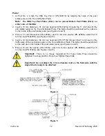
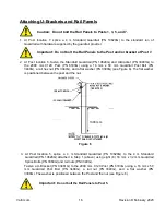
Page 14: ...5 4 Insert a 19 mm diameter x 64 mm hex head bolt PN 3717G through the 21 mm hole on the traffic side of the post plates ears on the Top and Bottom Posts The bolts should be positioned so the nuts ar...

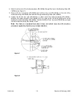
Page 15: ...PN 4254G and 10 mm lock washer PN 4258G under the 10 mm hex nut PN 6405G see Figures 4 and 5 4 Insert a 19 mm diameter x 64 mm hex head bolt PN 3717G through the 21 mm hole on the traffic side of the...

Page 16: ...t the 19 mm diameter x 76 mm hex head bolt PN 3718G through the 21 mm hole on the field side of the post plates ears on the Top and Bottom Posts The bolts should be positioned so the nuts are on the i...

Page 17: ...183G using a 16 mm x 50 mm Guardrail Post Bolt PN 3400G a rail hex nut PN 3340G and a flat washer PN 3300G see Figure 6 The flat washer is positioned between the post and the nut Figure 6 3 At Post lo...

Page 18: ...t 1 Cable Anchor Assembly The Cable Anchor Bracket PN 704A is secured to the 4 m Anchor Guardrail PN 29G by inserting the protruding hooks on the Cable Anchor Bracket PN 704A into the square slots in...

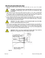
Page 19: ...the Bearing Plate PN 19258A 6 Tighten the 25 mm hex nuts PN 3910G on either end of the Cable Assembly PN 3000G Restrain the Cable Assembly PN 3000G with vise grips at the end being tightened to avoid...

Page 20: ...ead PN 995A have 3 holes in each Bracket Choose the hole in the Bracket that is closest to the predrilled hole in the HBA Top Post 1 PN 33462A while making sure that the edge of the Anchor Guardrail P...

Page 21: ...ble to Cable Assembly PN 3000G Loop back 165 mm of Tether Cable and attach two 2 Cable Clips PN 3371G to secure Tether Cable see Figure 11 and 12 TURN BACK 165 mm OF CABLE TO M KE LOOP PN 105038G THIM...

Page 22: ...g the Guardrail Extruder Head and has connecting plates cut at a 45 degree angle The 203 mm x 203 mm Bearing Plate at post 1 is correctly positioned with the tabs resting on the post plates ears of th...

Page 23: ...Valtir see p 8 10 3 Return to the repair site with genuine Valtir replacement parts 4 Burn off the Extruded Rail near the Guardrail Extruder head Attach a chain to the Guardrail Extruder Head Pull the...

Page 24: ...Valtir com 23 Revision D February 2023 EURO ET Drawing...

Page 25: ...Valtir com 24 Revision D February 2023 Notes...

Page 26: ...Valtir com 25 Revision D February 2023 Notes...

Page 27: ...Valtir com 26 Revision D February 2023 Notes...

Page 28: ...Materials and specifications are subject to change without notice Please contact Valtir to confirm that you are referring to the most current instructions USA Headquarters 1 214 589 8140 Middle East...

Reviews: