- 9 -
g
SYMBOLS
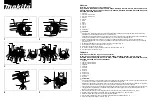
Carefully observe the symbols in fig. B and memorise their respective
meanings. Correct interpretation of the symbols allows safer use of
the machine.
1 Machine model
2 Technical data
3 Batch number (the first 2 figures of the batch number indicate the
year of manufacture)
4 Certification markings
V Volt
Hz Hertz
~
alternating current
Direct current
W Watt
mm millimetres
m metres
s seconds
kg kilograms
no
no load speed
min-1 revolutions per minute
dB decibel
We thank you for having purchased this power tool that will hereafter
also be referred to as “angle grinder”.
WARNING! The angle grinder is suitable, when used with the
appropriate discs, for the grinding, sanding, wire brushing, polishing
and abrasive cutting of materials such as metal, wood, plastic and
dry bricks.
It is prohibited to use dangerous materials in environments with risk
of fire/explosion
These instructions contain information deemed necessary for correct use,
knowledge and standard tool maintenance. They do not report information
on techniques for working with various materials. The user will find more
information in books and specialised publications or by attending courses.
COMPONENTS
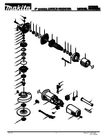
Refer to fig. A and the other figures attached to these instructions.
1.
Battery compartment
2.
Main handgrip
3.
Start/stop switch
5.
Disc holder shaft lock button
6.
Gear box
7.
Disc holder shaft
8.
Disc holder flange
9.
Disc lock flange
10.
Abrasive disc (not included)
11.
Disc locking key
12.
Seat for lateral handgrip
13.
Side handgrip
14.
Guard
15.
Air vents
25.
Guard locking lever
INSTALLATION
WARNING! The manufacturer is not liable for any direct and/or
indirect damage caused by incorrect connections.
WARNING! Before carrying out the following operations, make
sure that the battery is disconnected from the tool.
TRANSPORT
Always use the packaging or case (when provided) when transporting
the tool; this will protect it from impact, dust and humidity which can
compromise normal operation.
During transport, remove the abrasive disc, brush, etc. from the
machine.
HANDLING
Firmly grasp the handgrip (pos. 2) without using the switch; keep
the tool well away from your body and after use place it down gently
without hitting the disc.
SWITCHING ON
When choosing where to use the power tool, the following should be
considered:
- that the place is not damp and is protected from the weather.
- that there is a large working area free from obstacles.
- that there is good lighting.
- that it is used close to the main switch with residual current device.
- that the power supply system is earthed and conforms to the stan-
dards (only if the power tool is class I, which is equipped with an
earth cable plug).
- that the room temperature is between 10° and 35°C.
- that the environment is not in a flammable/explosive atmosphere.
Take out the machine and components and visually check that they
are perfectly intact; then proceed to thoroughly clean them in order to
remove any protective oils from metal surfaces.
ASSEMBLING GUARD PROVIDED WITH THE ANGLE GRINDER (fig.
C, pos.14)
WARNING! Only certain types of abrasive discs can be installed
on a given guard; follow the information provided in the “INSTRUC-
TIONS FOR USE - Disc Guard” chapter in the following pages.
1 Loosen the guard ring by pulling the locking lever outwards (pos.25).
2 Insert the guard (pos.14) into the housing of the bevel gear (pos.26)
3 Rotate the guard into the position indicated in fig.A (guard turned
towards the main handgrip).
4 Fasten the locking lever again.
5 Make sure that the protective device is properly secured.
Warning: The guard’s position can be adapted to specific work condi-
tions. Loosen the locking lever (pos.25) and turn the guard so as to
keep the working residues away from the body and protect the hands
SIDE HANDGRIP ASSEMBLY (pos.13)
The lateral handgrip can be assembled on any side on which there is
a threaded hole (pos.12); it is usually secured on the left in order to
grab hold with the left hand, but it can be assembled in the position
of your preference (e.g. for left-handed people). Insert the handgrip
into the threaded hole of the device and secure by screwing tightly.
ABRASIVE DISC ASSEMBLY (pos.10, not included)
1) Check that the rotation direction of the disc corresponds to that of
the angle grinder.
2) Turn the angle grinder upside down.
3) Check that the diameter of the seat of the 2 flanges and the hole of
the disc are the same size; to this end, it is better to measure using
a gauge (not included) and reading the technical data.
4) Temporarily block the rotation of the motor shaft by pressing the
button (pos.5) and unscrew the disc lock flange (pos.9). Do not
disassemble the disc hold flange (pos.8).
5) Insert the abrasive disc (pos.10) onto the shaft (pos.7) and place
it on the disc hold flange (pos.8). Make sure the disc hold flange
rabbet goes into the disc hole.
6) Follow fig. D to correctly place the disc lock flange (pos.9) depending
on the number of discs you intend to use. Screw the disc block flange
(pos.9) and fix it carefully using the fixture key (pos.11): while doing
so, keep the shaft block button pressed (pos.5). The locking key
should be inserted with the two pins, in the disc lock flange holes.
7) Rotate by hand and check that the disc is well centred and well
secured by the flanges.
8) Keeping the angle grinder away from the body, carry out a dry test
run for 1 minute.


