background image

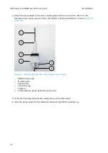
90°

1

2

4

3

Figure 16 Duct installation overview

1

Make sure there is a minimum clearance of 5 m (16.5 ft) between the probe head and any
possible humidifier. Avoid installing in a location where condensation can fall on the probe
head inside the duct.

2

Maximum air flow speed: 50 m/s.

3

Avoid installing the probe in dead legs. Supersaturation can occur in areas where there is
no air flow.

4

Install the probe head in a 90° angle to prevent condensation from travelling to the sensor
along the mounting pipe. Position the sensor as close to the middle of the duct as
possible.

4.9.3 Mounting HMP9 probe head with Duct Installation Kit

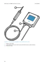
1. Loosen the sealing gland on the back of the pipe by turning it 1.5 full rotations. Do not

detach the gland to avoid dislocating the sealing ring.

HMP Series with MMP8 and TMP1 User Guide

M212022EN-F

34

Summary of Contents for HMP Series

Page 1: ...M212022EN F User Guide Vaisala Indigo compatible humidity and temperature probes HMP Series with MMP8 and TMP1...

Page 2: ...ange without prior notice Local rules and regulations may vary and they shall take precedence over the information contained in this document Vaisala makes no representations on this document s compli...

Page 3: ...tion functions 18 4 Installation 20 4 1 Probe holder ASM213582 21 4 1 1 Mounting the probe body using probe holder ASM213582 21 4 2 Wiring 22 4 3 HMP1 probe 23 4 4 HMP3 probe 24 4 5 HMP4 probe 25 4 6...

Page 4: ...leshooting 61 8 1 Problem situations 61 8 2 Error messages 61 8 3 Restoring factory default settings 63 9 Technical data 64 9 1 HMP1 specifications 64 9 2 HMP3 specifications 67 9 3 HMP4 specification...

Page 5: ...A 6 Exception responses 109 A 7 Modbus communication examples 110 Maintenance and calibration services 113 Warranty 113 Technical support 113 Recycling 113 Table of contents 3...

Page 6: ...Figure 24 HMP5 diagnostics in Insight advanced mode 44 Figure 25 Probe attached to Indigo200 series transmitter directly 45 Figure 26 Probe attached to Indigo200 series transmitter with a cable 46 Fi...

Page 7: ...unction of temperature 82 Figure 49 HMP8 temperature measurement accuracy over full range 82 Figure 50 HMP8 probe dimensions 84 Figure 51 Optional ball valve installation kit dimensions 85 Figure 52 H...

Page 8: ...4 output parameters 72 Table 22 HMP4 compliance 73 Table 23 HMP4 mechanical specifications 73 Table 24 HMP5 measurement performance 74 Table 25 HMP5 operating environment 75 Table 26 HMP5 inputs and o...

Page 9: ...rts 96 Table 64 HMP7 accessories 96 Table 65 HMP7 spare parts 97 Table 66 HMP8 accessories 97 Table 67 HMP8 spare parts 97 Table 68 HMP9 accessories 97 Table 69 MMP8 accessories 98 Table 70 MMP8 spare...

Page 10: ...HMP Series with MMP8 and TMP1 User Guide M212022EN F 8...

Page 11: ...AP technology page 17 Chemical purge page 17 Condensation prevention functions page 18 Mounting the probe body using probe holder ASM213582 page 21 Configuring condensation prevention page 42 HMK15 Hu...

Page 12: ...t for HMP3 and MMP8 probe models 1 2 Related manuals Table 2 Related manuals Document code Name M211982EN HMP Series with MMP8 and TMP1 Quick Guide M211877EN Indigo201 Analog Output Transmitter User G...

Page 13: ...t you need to take some notes during the task 1 4 Trademarks Vaisala and HUMICAP are registered trademarks of Vaisala Oyj Modbus is a registered trademark of Schneider Automation Inc All other product...

Page 14: ...2 3 4 5 6 7 8 Figure 1 Probe parts 1 Protection cap remove before use 2 5 pin M12 connector 3 Probe body with type label 4 Status indicator LED Green Power on and probe online flashes when communicati...

Page 15: ...chemical purge function Output parameter is available on this model Output parameter is available on this model but its value is unavailable when condensation prevention functions are warming the sens...

Page 16: ...transmitters Touchscreen display for real time data viewing and configuration Support for 2 probes simultaneously 4 configurable analog outputs 2 configurable relays Ethernet connection with web inter...

Page 17: ...any objects inside the equipment housing Avoid touching component contacts or connectors when working with the device 2 7 Regulatory statements 2 7 1 FCC Part 15 compliance statement This equipment h...

Page 18: ...r s authority to operate the equipment CAUTION This device complies with part 15 of the FCC Rules Operation is subject to the following two conditions 1 This device may not cause harmful interference...

Page 19: ...ndensation prevention functions that are a key element in achieving an excellent stability and good condensation resistance in high humidity applications The integrated sensor arrangement on the HMP1...

Page 20: ...ameters become unavailable unless external temperature information is provided to the probe The output parameters become available again 4 minutes after the warming is stopped Sensor warming is intend...

Page 21: ...ating is not active if supply voltage is below 18 V DC For example this is the case when HMP7 probe is connected to Insight software using the Indigo USB Adapter More information Configuring condensat...

Page 22: ...vents measurement inaccuracy caused by heat conduction along the cable Probe mounting options are model specific 1 2 3 4 Figure 2 Example installation 1 Mount the probe head horizontally to prevent an...

Page 23: ...8 in probe body 5 Top of the probe holder with 2 hex screws 4 mm socket 52 2 05 5 9 0 23 4 mm hex 57 2 24 38 1 50 mm in 25 mm Figure 3 Probe holder ASM213582 dimensions 4 1 1 Mounting the probe body u...

Page 24: ...base part using screws 6 Insert the probe body in the holder 7 Place the top part on the base and tighten the hex screws with a 4 mm Allen key 4 2 Wiring 1 5 3 4 2 Figure 4 M12 5 pin A coded male con...

Page 25: ...t 4 3 HMP1 probe 112 4 41 162 6 38 25 0 98 M12 5 5 0 20 16 0 63 50 1 97 mm in Figure 6 HMP1 probe dimensions Vaisala HUMICAP Humidity and Temperature Probe HMP1 is designed for ambient measurement in...

Page 26: ...e HMP3 is a general purpose probe designed for various industrial processes The probe structure allows for replacing the sensor without tools making it suitable for applications such as paint booths a...

Page 27: ...aling ring 22 27 1 5 Cu 12 0 47 32 mm 27 mm mm in Figure 8 HMP4 probe dimensions Vaisala HUMICAP Humidity and Temperature Probe HMP4 is designed for high pressure applications such as compressed air s...

Page 28: ...mm in Figure 10 Optional mounting flange 210696 dimensions Vaisala HUMICAP Humidity and Temperature Probe HMP5 is designed for high temperature applications such as baking ovens pasta dryers and indus...

Page 29: ...humidity such as drying and test chambers combustion air and other humidifiers and meteorological measurements where measurement performance and chemical tolerance are essential Temperature measureme...

Page 30: ...n exchange membrane fuel cells PEMFC Humidity measurements in fuel cell applications are performed in a high humidity environment typically over 80 relative humidity Performing humidity measurements i...

Page 31: ...r systems refrigerant dryers and other pressurized industrial applications where easy insertion and removal of the probe and adjustable installation depth into the pipeline are needed Temperature meas...

Page 32: ...t to the same direction as the ball valve body when installing 2 Extension nipple threads G1 2 ISO228 1 and R1 2 ISO7 1 3 Ball valve body When tightening the assembly turn only from the ball valve bod...

Page 33: ...the ball valve assembly only from the ball valve body CAUTION 4 If you need to cap the ball valve assembly before installing or after removing the probe attach a blanking nut to close the top of the...

Page 34: ...ng temperature of probe body 40 60 C 40 140 F Integrated filter non replaceable Do not damage the probe head by bending crushing or striking it Avoid overtightening when installing the probe head thro...

Page 35: ...the cable gland to finger tightness 6 Tighten the nut of the cable gland with a 13 mm wrench until the probe head stops moving Do not overtighten 4 9 2 Overview of HMP9 Duct Installation Kit Duct Ins...

Page 36: ...ad legs Supersaturation can occur in areas where there is no air flow 4 Install the probe head in a 90 angle to prevent condensation from travelling to the sensor along the mounting pipe Position the...

Page 37: ...unting flange on the pipe Make sure the black sealing surface faces the probe head 4 Make a 14 mm 0 55 in hole in the duct or chamber wall 5 Push the probe head and pipe into the duct or chamber and a...

Page 38: ...ecting water ingress and preventing free water formation is crucial The measurement is independent of oil type and age MMP8 can also output ppm the average mass concentration of water in oil Vaisala h...

Page 39: ...n shield DTR502B protects the sensors on the probe head from solar radiation and precipitation in outdoor installations It provides excellent ventilation while blocking both direct and reflected solar...

Page 40: ...mm in Figure 19 DTR502B dimensions 4 12 1 Mounting probe head inside DTR502B 3 mm and 5 mm Allen keys Crosshead screwdriver DTR502B solar radiation shield is compatible with the probe heads of HMP3 HM...

Page 41: ...ring 4 Probe head 5 Sensor head support 1 Mount the solar radiation shield in the measurement location using the provided mounting accessories screws and washers You can mount the radiation shield to...

Page 42: ...3 5 6 Figure 21 HMP9 probe head with sensor head support 215130 1 HMP9 probe head 2 Mounting nut 3 Sealing ring 4 Fastening ring 5 Cable tie 6 Cable between probe head and probe body 3 Insert the fas...

Page 43: ...system and Indigo USB adapter item code USB2 or Vaisala USB cable item code 242659 required Download Vaisala Insight software at www vaisala com insight 5 2 Connecting to Insight software Computer wit...

Page 44: ...tware is the recommended way to change the probe configuration After connecting the probe select Configure Device to access the configuration options Available configuration options include all of the...

Page 45: ...or advanced The data can be very useful when diagnosing issues together with Vaisala support particularly the diagnostic files Diagnostic files If Insight is in Advanced Mode you can retrieve the foll...

Page 46: ...Figure 24 HMP5 diagnostics in Insight advanced mode HMP Series with MMP8 and TMP1 User Guide M212022EN F 44...

Page 47: ...obes can be attached directly A cable may also be used to connect the probe After connecting the probe use the wireless configuration interface to configure the transmitter 1 2 3 4 5 6 Figure 25 Probe...

Page 48: ...ched to Indigo200 series transmitter with a cable 1 Cable to probe head 2 Locking wheel insert cable hold in place and turn the wheel counterclockwise 3 Connection cable HMP Series with MMP8 and TMP1...

Page 49: ...le is recommended for strain relief 2 Turn the locking wheel of the transmitter to lock the probe or cable in place Do not turn the probe or the cable itself as that will damage the connectors 3 If yo...

Page 50: ...nnected After connecting a probe use the touchscreen interface or the web user interface to configure the transmitter 3 4 1 2 5 Figure 28 Attaching probes to Indigo500 transmitter 1 Probe connection c...

Page 51: ...hese precautions Avoid touching the filter If you need to touch the filter always wear clean gloves cotton rubber or similar material Keep the filter free of any grease or oil Do not scrape the probe...

Page 52: ...ensor New compatible filter Clean lint free gloves 11 3 RH and 75 5 RH humidity references using Vaisala HMK15 Humidity Calibrator Computer with Microsoft Windows operating system and Vaisala Insight...

Page 53: ...need to revert the probe to factory settings after replacing the sensor yourself write down the values on the Adjustment data page beforehand and enter them again after applying the factory settings...

Page 54: ...Click table cell A2 and enter the value of the humidity reference 75 5 d Click table cell B2 and enter the RH measured by the probe 13 Click outside the table to commit the adjustment 14 Remove the pr...

Page 55: ...stment in more than two points is available when using Insight software in Advanced Mode If you are adjusting in more than one humidity point make sure the first two points are at least 10 RH apart Th...

Page 56: ...this adapter attached use the 13 5 mm hole on the salt jar cover Figure 30 HMP5 calibration with HMK15 using 211302SP adapter 12 mm 0 47 in diameter probes where the leg pins are shorter than 7 mm can...

Page 57: ...tabilization This is typically only practical for 1 point calibration 7 4 3 Adjusting measurement with Insight software Computer with Microsoft Windows operating system and Vaisala Insight software in...

Page 58: ...Yes to store the adjustment in the probe 8 Check the message that appears at the top of the screen If the message indicates that the adjustment is activated successfully your adjustment is stored in t...

Page 59: ...less connection menu in your mobile device or computer and select Indigo_ID xx transmitter specific SSID from the list of available connections c If the wireless configuration interface does not launc...

Page 60: ...easurement has stabilized f Enter the value of the first reference into the Reference value point 1 field Select outside the text box when done The probe automatically enters the measured values for t...

Page 61: ...Figure 32 Calibration page in the Indigo200 wireless configuration interface Chapter 7 Maintenance 59...

Page 62: ...onitor the reading to see when the measurement has stabilized e Enter the value of the first reference into the Reference value point 1 field Select outside the text box when done The probe automatica...

Page 63: ...to Insight software or an Indigo transmitter and read the error message s See Vaisala Insight software page 41 and Error messages page 61 Probe status indicator LED is off even though power is on Pro...

Page 64: ...ation settings corrupted Device settings corrupted Sensor coefficients corrupted Non volatile memory read write failure Hardware fault Errors Temperature measurement error Readings from sensors missin...

Page 65: ...supply voltage is stable and operating environment is within specification Unexpected device restart Status messages Calibration is about to expire Shown by calibration reminder functionality Calibrat...

Page 66: ...t 23 C 73 4 F 1 2 0 2 C 0 36 F Factory calibration uncertainty 3 0 1 C 0 18 F at 23 C 73 4 F 1 Defined against calibration reference Including non linearity hysteresis and repeatability 2 In typical r...

Page 67: ...ating IP50 Limited protection against dust 1 Consult Vaisala if other chemicals are present Consider safety regulations with flammable gases Table 8 HMP1 inputs and outputs Property Description Value...

Page 68: ...g Wet bulb temperature C Table 10 HMP1 compliance Property Value Description EU directives EMC Directive 2014 30 EU RoHS Directive 2011 65 EU EMC compatibility EN 61326 1 industrial environment Compli...

Page 69: ...40 248 F Accuracy 1 5 0 1 C 0 18 F Factory calibration uncertainty 2 0 1 C 0 18 F at 23 C 73 4 F 1 Defined against calibration reference Including non linearity hysteresis and repeatability 2 Defined...

Page 70: ...13 HMP3 operating environment Property Description Value Operating temperature of probe head 40 120 C 40 248 F Operating temperature of probe body 40 80 C 40 176 F Storage temperature 40 80 C 40 176...

Page 71: ...t point temperature at 1 atm C Water concentration wet basis vol Dew point temperature at 1 atm C Water mass fraction ppmw Dew point temperature difference C Water vapor pressure hPa Enthalpy kJ kg Wa...

Page 72: ...P3 probe dimensions 9 3 HMP4 specifications Table 18 HMP4 measurement performance Property Description Value Relative humidity Measurement range 0 100 RH Accuracy at 23 C 73 4 F 1 0 8 RH 0 90 RH Facto...

Page 73: ...available with this sensor 4 Exposing temperature sensor to temperatures outside 20 150 C 4 302 F may cause permanent additional deviation of 0 1 C 0 18 F 0 0 0 5 1 0 1 5 2 0 2 5 3 0 40 30 20 10 0 10...

Page 74: ...roperty Description Value Operating voltage 15 30 V DC Current consumption 10 mA typical 500 mA max Digital output RS 485 non isolated Protocols Modbus RTU Table 21 HMP4 output parameters Output param...

Page 75: ...chanical specifications Property Description Value Connector M12 5 pin A coded male Fitting body M22 1 5 or NPT1 2 Weight 530 g 18 7 oz Materials Probe AISI 316 Probe body AISI 316 Cable jacket FEP 13...

Page 76: ...y at 23 C 73 4 F 1 4 0 1 C 0 18 F Factory calibration uncertainty 2 0 1 C 0 18 F at 23 C 73 4 F Sensor Pt100 RTD Class F0 1 IEC 60751 1 Defined against calibration reference Including non linearity hy...

Page 77: ...10 0 10 20 30 40 50 60 70 80 90 100 110 120 130 140 150 160 170 180 0 5 70 60 50 Figure 43 HMP5 temperature measurement accuracy over full range Table 25 HMP5 operating environment Property Descripti...

Page 78: ...ature at 1 atm C Water concentration wet basis vol Dew point temperature at 1 atm C Water mass fraction ppmw Dew point temperature difference C Water vapor pressure hPa Enthalpy kJ kg Water vapor satu...

Page 79: ...ft or 10 m 32 8 ft 5 0 2 mm in Figure 44 HMP5 probe dimensions 9 5 HMP7 specifications Table 30 HMP7 measurement performance Property Description Value Relative humidity Measurement range 0 100 RH Acc...

Page 80: ...iations possible see calibration certificate 3 Chemical purge feature available with this sensor 4 H2O2 resistant With HUMICAP 180VC sensor accuracy is not specified below 20 C 4 F operating temperatu...

Page 81: ...able for outdoor use Measurement environment For air nitrogen hydrogen argon helium oxygen and vacuum 1 IP rating of probe body IP66 Dust tight Protected from powerful water jets from any direction 1...

Page 82: ...por pressure hPa Enthalpy kJ kg Water vapor saturation pressure hPa Mixing ratio g kg Wet bulb temperature C Table 34 HMP7 compliance Property Value Description EU directives EMC Directive 2014 30 EU...

Page 83: ...Table 36 HMP8 measurement performance Property Description Value Relative humidity Measurement range 0 100 RH Accuracy at 23 C 73 4 F 1 0 8 RH 0 90 RH Factory calibration uncertainty 2 0 5 RH 0 40 RH...

Page 84: ...sensor to temperatures outside 20 150 C 4 302 F may cause permanent additional deviation of 0 1 C 0 18 F 0 0 0 5 1 0 1 5 2 0 2 5 3 0 40 30 20 10 0 10 20 30 40 50 60 70 80 90 100 110 120 Accuracy RH Te...

Page 85: ...and outputs Property Description Value Operating voltage 15 30 V DC Current consumption 10 mA typical 500 mA max Digital output RS 485 non isolated Protocols Modbus RTU Table 39 HMP8 output parameters...

Page 86: ...cations Property Description Value Connector M12 5 pin A coded male Probe fitting ISO1 2 and NPT1 2 fittings included Weight 512 g 18 1 oz Materials Probe AISI 316L Probe body AISI 316L Cable jacket F...

Page 87: ...RH Factory calibration uncertainty 2 0 7 RH 0 40 RH 1 RH 40 95 RH Non linearity 0 4 RH T63 response time 3 15 s Sensor HUMICAP I Temperature Measurement range 40 120 C 40 248 F Accuracy at 23 C 73 4...

Page 88: ...100 110 120 0 5 Figure 53 HMP9 temperature measurement accuracy over full range Table 43 HMP9 operating environment Property Description Value Operating temperature of probe body 40 60 C 40 140 F Oper...

Page 89: ...humidity g m3 Relative humidity RH Absolute humidity at NTP g m3 Relative humidity dew frost RH Dew point temperature C Temperature C Dew frost point temperature C Water concentration ppmv Dew frost...

Page 90: ...68 g 2 40 oz Probe cable length 2 m 6 6 ft Materials Probe AISI 316L Probe body PBT Cable overmolds FEP 112 4 41 Probe cable 2 m 6 56 ft 25 0 98 M12 5 94 3 70 2 4 0 094 5 0 05 0 20 0 002 16 0 63 Atta...

Page 91: ...ity hysteresis and repeatability See accuracy graph below 0 0 0 1 0 01 0 2 0 02 0 3 0 03 0 4 0 5 0 6 0 7 0 8 0 9 1 0 0 04 a w reading accuracy aw reference T 0 80 C T 40 0 C 80 180 C Figure 55 MMP8 Aw...

Page 92: ...eters Relative saturation RS Temperature C Water activity Water mass fraction ppmw Table 51 MMP8 compliance Property Value Description EU directives EMC Directive 2014 30 EU RoHS Directive 2011 65 EU...

Page 93: ...5 5 0 2 262 10 32 224 8 82 35 179 1 37 7 05 35 1 37 13 5 0 53 Fitting body ISO1 2 or NPT1 2 12 0 47 mm in Figure 56 MMP8 dimensions 9 9 TMP1 specifications Table 53 TMP1 measurement performance Prope...

Page 94: ...ature measurement accuracy over full range Table 54 TMP1 operating environment Property Description Value Operating temperature of probe body 40 80 C 40 176 F Operating temperature of probe head 70 18...

Page 95: ...liance Property Value Description EU directives EMC Directive 2014 30 EU RoHS Directive 2011 65 EU EMC compatibility EN 61326 1 industrial environment Compliance marks CE China RoHS RCM WEEE Table 57...

Page 96: ...e dimensions 135 370 5 31 14 56 50 1 96 75 2 95 mm in Figure 59 Optional duct kit 215003 dimensions 9 10 Accessories and spare parts Information on spare parts accessories and calibration products is...

Page 97: ...0 6 m 244669SP Flat cable M12 5F M12 5M 1 m CBL210493SP Vaisala Indigo USB adapter 1 USB2 1 Vaisala Insight software for Windows available at www vaisala com insight HMP3 Table 59 HMP3 accessories De...

Page 98: ...red stainless steel filter HM47280SP Stainless steel grid HM47453SP Metallized PPS plastic grid with stainless steel mesh filter DRW010281SP Metallized PPS plastic grid filter DRW010276SP HMP7 Table 6...

Page 99: ...1 2 welding joint BALLVALVE 1 Table 67 HMP8 spare parts Description Item code Sintered stainless steel filter HM47280SP Stainless steel grid HM47453SP Metallized PPS plastic grid with stainless steel...

Page 100: ...are parts Description Item code Stainless steel grid filter HM47453 Stainless steel grid filter for high flow rates 1 m s 220752 TMP1 Table 71 TMP1 accessories Description Item code Duct installation...

Page 101: ...e 73 Modbus function codes Function code decimal Function code hexadecimal Name Notes 03 03hex Read Holding Registers Class 0 16 10hex Write Multiple Registers Class 0 43 14 2Bhex 0Ehex Read Device Id...

Page 102: ...it integer value should be read and written in a single Modbus transaction Reading the measurement data registers with incorrect floating point format setting may occasionally result in correct lookin...

Page 103: ...a registers Table 75 Floating point measurement data registers read only Register number Address Register description Data format Unit 1 0000hex Relative humidity 32 bit float RH 0001hex 3 0002hex Tem...

Page 104: ...ty 32 bit float 001Dhex 31 001Ehex Dew point temperature difference 32 bit float C 001Fhex 33 0020hex Absolute humidity at NTP 32 bit float g m3 0021hex 35 0022hex Water concentration in oil 32 bit fl...

Page 105: ...t signed integer 100 0 g m3 265 0108hex Mixing ratio 16 bit signed integer 100 0 g kg 266 0109hex Wet bulb temperature 16 bit signed integer 100 0 C 267 010Ahex Water concentration 16 bit signed integ...

Page 106: ...at Unit Valid range General 1287 0506hex Condensation prevention on off Enables the condensation prevention heating functions of the device When warming is active values of output parameters that depe...

Page 107: ...terval 32 bit float Unit min 10 14400 0305hex 1283 0502hex Interval purge on off 16 bit boolean 0 Off 1 On 1284 0503hex Startup purge on off 16 bit boolean 0 Off 1 On Filtering 795 031Ahex Measurement...

Page 108: ...0 5 9600 6 19200 7 38400 8 57600 9 115200 1539 0602hex Parity data stop bits enum 0 None 8 1 1 None 8 2 2 Even 8 1 3 Even 8 2 4 Odd 8 1 5 Odd 8 2 default 1 None 8 2 1540 0603hex Response delay 16 bit...

Page 109: ...s made to device settings or adjustments 0206hex 520 0207hex RH measurement status 16 bit signed integer 0000hex Status OK 0001hex Measurement is not available 0002hex Measurement is not reliable 0004...

Page 110: ...egisters to verify the functionality of your Modbus implementation Table 80 Modbus test registers read only Register number Address Register description Data format Test value 7937 1F00hex Signed inte...

Page 111: ...ormat Empty string if not set valid 130 82hex CalibrationText 1 Vaisala HEL Calibration information text Empty string if not set valid 1 Vaisala specific device information A 6 Exception responses Tab...

Page 112: ...ter address 04hex Number of data bytes 00hex 7Ahex Value of first register least significant word 00hex Number of 16 bit registers to read 2 E1hex 02hex 41hex Value of second register most significant...

Page 113: ...bus RTU checksum 6Ehex Value for first register least significant word ADhex 14hex 44hex Value for second register least significant word silence for 3 5 bytes End of Modbus RTU frame 75hex 4Ehex Modb...

Page 114: ...ion Data format Two 16 bit Modbus registers interpreted as IEEE 754 binary32 floating point value least significant word first Value to write 44756E14hex 981 72 hPa HMP Series with MMP8 and TMP1 User...

Page 115: ...nty Please observe that any such warranty may not be valid in case of damage due to normal wear and tear exceptional operating conditions negligent handling or installation or unauthorized modificatio...

Page 116: ......

Page 117: ......

Page 118: ...www vaisala com...

Reviews: