38
Instructions on commissioning, maintenance, and troubleshooting for auroSTOR 0020111119_02
6.8.4 Connection of the solar pump
3
3
3
1
2
3
4
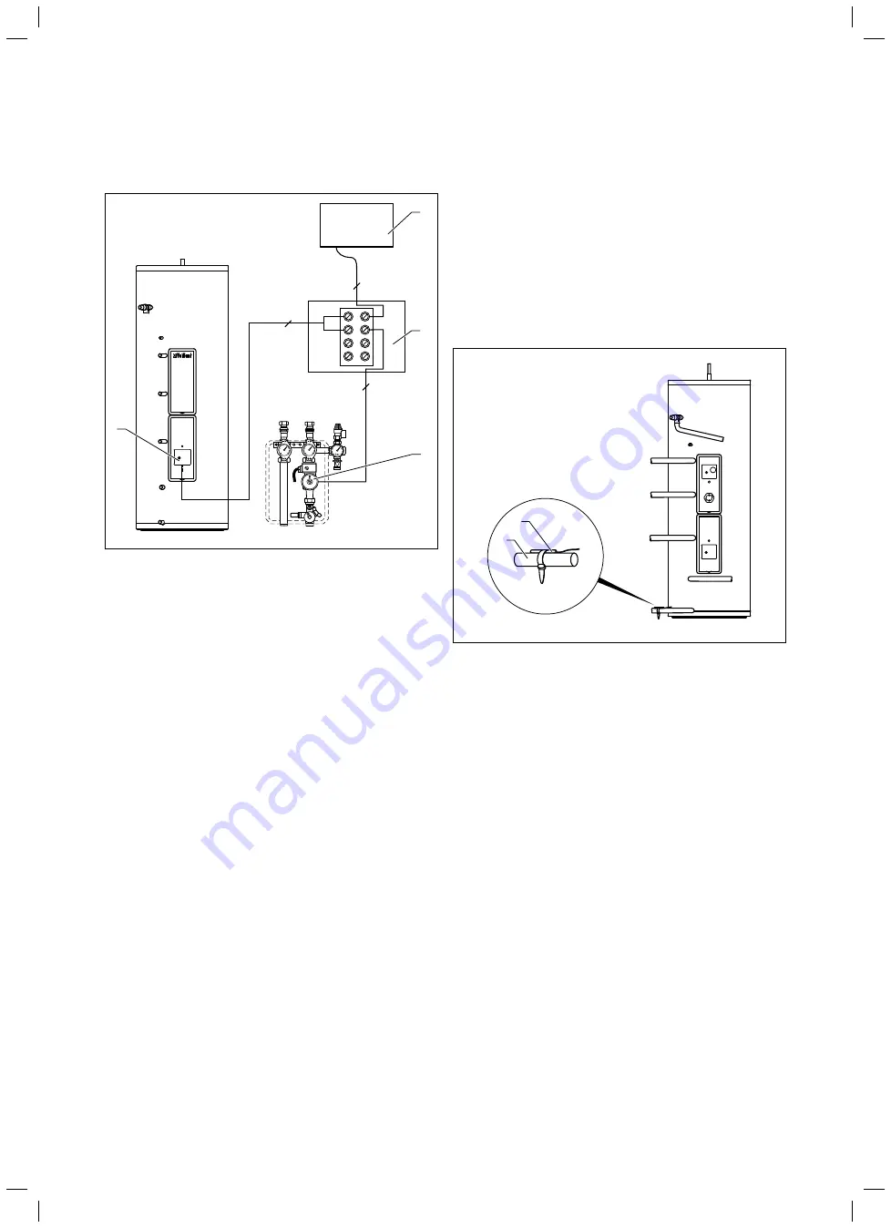
Fig. 6.15 Connection diagram for solar pump
Key
1 VRS 560/2 or VR 68/2
2 Terminal strip for series circuit to solar pump via TCO solar
circuit
3 Solar
pump
4 Solar circuit thermal cut-out (TCO)
Connection wiring diagrams 1, 2, 3, 4, and 6:
>
Next to the cylinder, install the VRS 560/2 solar control-
ler (
1
).
Connection wiring diagram 5:
>
Next to the cylinder, install the VR 68/2 solar module (
1
).
>
Dismantle the cover of the VRS 560/2 solar controller or
the VR 68/2 solar module.
>
Dismantle the cover of the solar circuit thermal
cut-out (
4
).
>
Connect the solar pump (
3
) in series with the provided
solar circuit thermal cut-out. To do so, use a protected
terminal strip (
2
) and 3-core cable provided by the cus-
tomer.
The solar pump and solar circuit thermal cut-out must
be earthed using a protective earth.
>
You must carry out a protective earth test.
Connection wiring diagrams 1, 2, 3, 4, and 6
(VRS 560/2):
>
Connect the terminal strip with the terminal
Kol 1-P
of
the VRS 560/2 (
1
).
Connection wiring diagram 5 (VR 68/2)
:
>
Connect the terminal strip with the terminal
Kol 1-P
of
the VR 68/2 (
1
).
6.8.5 Connecting up the solar yield temperature
sensor
1
2
Fig. 6.16 Solar yield temperature sensor
Key
1 Solar yield temperature sensor
2 Solar
return
>
Mount the solar yield temperature sensor (
1
) on the
return line (
2
) of the solar circuit.
Connection wiring diagrams 1, 2, 3, 4, and 6 (VRS 560/2):
>
Connect the solar yield temperature sensor to the yield
(
"Ertrag"
) terminal of the VRS 560/2 solar controller.
Connection wiring diagram 5 (VR 68/2):
>
Connect the solar yield temperature sensor to the yield
(
"Ertrag"
) terminal of the VR 68/2 solar module.
6 Installation


