Instructions on commissioning, maintenance, and troubleshooting for auroSTOR 0020111119_02
35
Solar circuit control system
Solar circuit control via one of the following means:
– The auroMATIC 560/2 differential temperature-cont-
rolled control set for solar-aided hot water production
– The VRC weather compensator with VR 68/2.
i
The temperature sensors VR 10 (cylinder sensor)
and VR 11 (collector sensor) are supplied with the
VRS 560/2 solar controller or VR 68/2 solar
module.
Control system of the heating circuits
The heating circuits can be controlled via Vaillant pro-
grammable room thermostats or weather compensators
in conjunction with the Vaillant range of eBUS-compati-
ble gas-fired wall-hung boilers. You can also use tested
standard operating elements (see above).
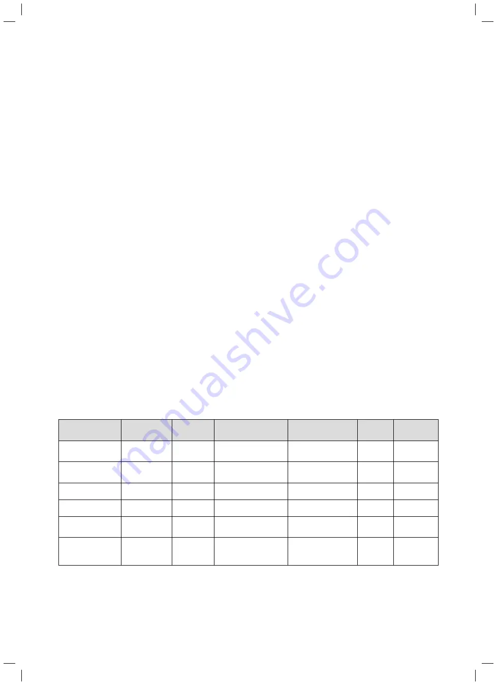
For an overview of the combination options for these
control components, see Tab. 6.5.
i
All wiring must be carried out in accordance
with BS 7671: "Requirements for electrical instal-
lations" (IEE wiring regulations, current edition).
i
For the wiring of the solar pump, solar
controller, and solar pump thermal cut-outs on
the cylinder (see connection wiring diagrams 1 to
6,
¬ section 6.8.6
), an additional terminal strip
is required.
Hot water reheating control
Hot water primary heating control via the auroMATIC
560/2 differential temperature-controlled control set for
solar-aided hot water production with demand-control-
led primary heating for Vaillant gas-fired wall-hung boil-
ers. Alternatively, via a Vaillant dual-circuit eBUS con-
troller or a timer (from a third-party manufacturer).
Gas-fired
wall-hung boiler
Wiring via
Solar circuit
control sys-
tem
Control system of
the heating circuits
Solar cylinder primary
heating control sys-
tem
Hydraulic
plan
Connection
wiring dia-
gram
Vaillant ecoTEC,
eBUS-compatible
Vaillant Control
Centre
VRS 560/2
Vaillant dual-channel
eBUS controller
Vaillant dual-channel
eBUS controller with
Vaillant Control Centre
S plan
1 ¬ Fig. 6.17
Vaillant ecoTEC,
eBUS-compatible
Vaillant Control
Centre
VRS 560/2
Vaillant dual-channel
eBUS controller
Vaillant dual-channel
eBUS controller with
Vaillant Control Centre
Y plan
2 ¬ Fig. 6.18
Vaillant ecoTEC,
eBUS-compatible
Vaillant Control
Centre
VRS 560/2
Vaillant dual-channel
eBUS controller
VRS 560/2 with Vaillant
Control Centre
S plan
3 ¬ Fig. 6.19
Vaillant ecoTEC,
eBUS-compatible
Vaillant Control
Centre
VRS 560/2
Vaillant dual-channel
eBUS controller
VRS 560/2 with Vaillant
Control Centre
Y plan
4 ¬ Fig. 6.20
Vaillant ecoTEC,
eBUS-compatible
VR 61/2 and
VR 68/2
VRC with
VR 68/2
Vaillant dual-channel
eBUS controller
Vaillant dual-channel
eBUS controller and
VR 68/2
S plan
5 ¬ Fig. 6.21
Non-eBUS-compati-
ble boiler from a
third-party manufac-
turer
Standard cabling
box
VRS 560/2
Programmable timer and
room thermostat
VRS 560/2
S or Y plan
6 ¬ Fig. 6.22
Tab. 6.5 Options for combining control components
Installation 6


