Instructions on commissioning, maintenance, and troubleshooting for auroSTOR 0020111119_02
13
3
3
3
1
2
3
4
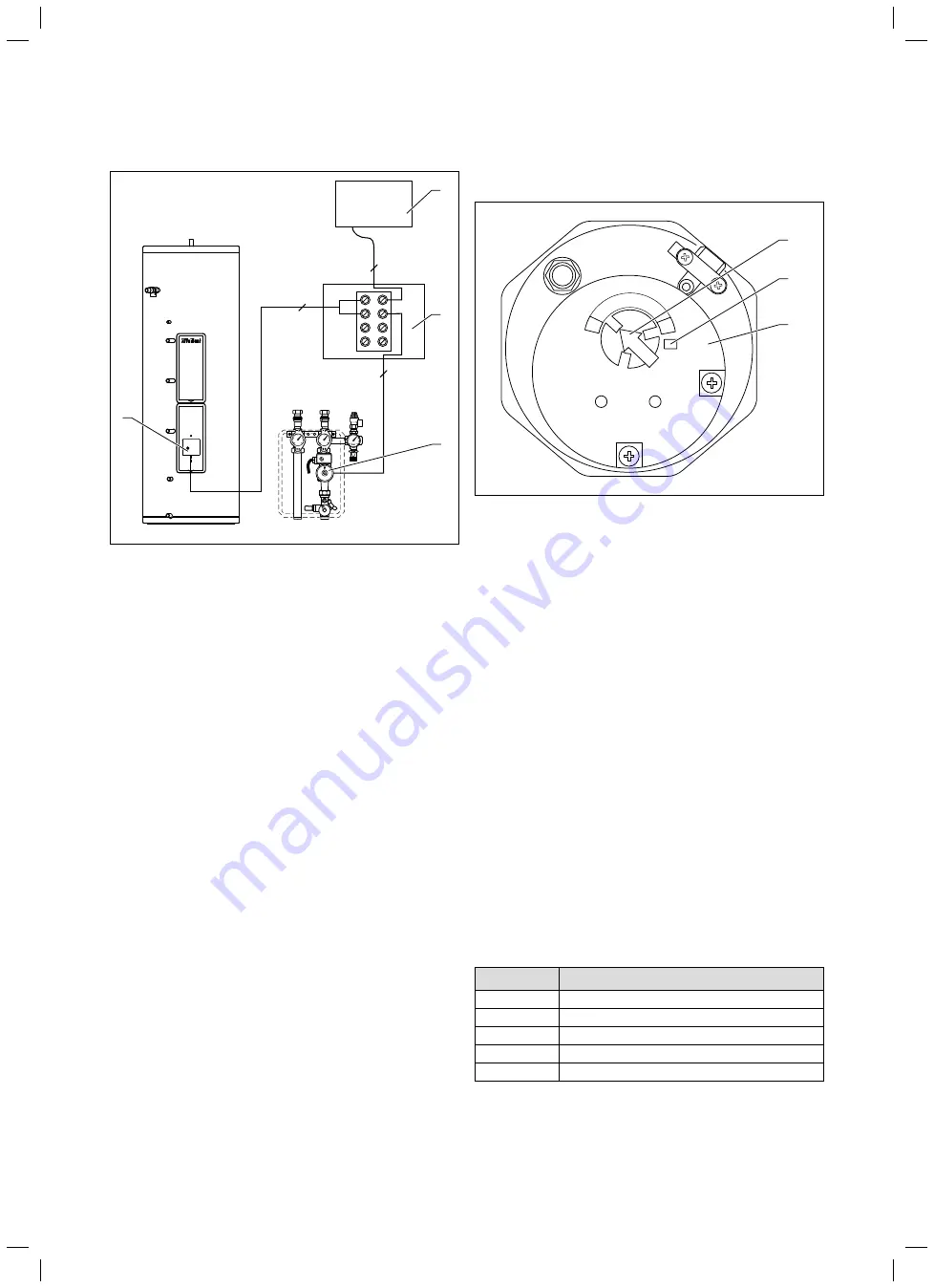
Fig. 4.3 Connection diagram for solar pump
Key
1 Solar controller or solar module
2 Terminal strip for series circuit to solar pump via TCO solar
circuit
3 Solar
pump
4 Solar circuit thermal cut-out
i
You must connect the solar pump to the solar
controller via the solar circuit thermal cut-out
(
5
) (
¬ section 6.8
). The thermostat switches the
solar pump off if the hot water temperature in
the cylinder exceeds 80 ºC. Set the maximum
cylinder temperature (MAXT 1)
to 75 °C (factory setting) on the auroMATIC
VRS 560 solar controller.
Electric immersion heater
1
2
3
4
5
1
2
3
Fig. 4.4 Electric immersion heater operating elements
Key
1 Electric immersion heater temperature controller
2 Electric immersion heater TCO reset button
3 Electric immersion heater
The cylinder is equipped with an additional electric
immersion heater (
3
) with a heating output of 3 kW. The
electric immersion heater is located behind the top front
cladding. The electric immersion heater is designed for
use in unvented cylinders and has a thermostat with a
temperature controller (
1
) and a thermal cut-out (TCO)
with a reset button (
2
).
i
If you need to make a replacement, you must
use the correct electric immersion heater with a
thermal cut-out for overheating protection. The
seal of the electric immersion heater must also
always be replaced. Use only original replace-
ment parts from Vaillant Ltd.
Setting the hot water temperature
You can set the hot water temperature by pointing the
arrow on the temperature controller (
1
) of the electric
immersion heater to a number between 1 and 5. The fol-
lowing table contains the approximate hot water temper-
ature for each of the five settings.
Setting
Hot water temperature
1
20 °C
2
35 °C
3
45 °C
4
60 °C
5
68 °C
Table 4.1 Setting the hot water temperature
Description of the components 4


