background image

7. Control menu 

The Robin 300 Plasma Spot is equipped with the QVGA Robe touch screen with battery backup which 

 allows to set the fixture´s behaviour  according  to your needs, obtain information on its operation, test its vari

-

ous parts and lastly program it, if it has to be used in a stand-alone mode. 

The fixture´s menu can be controlled either by the control buttons or directly by touching the icon.

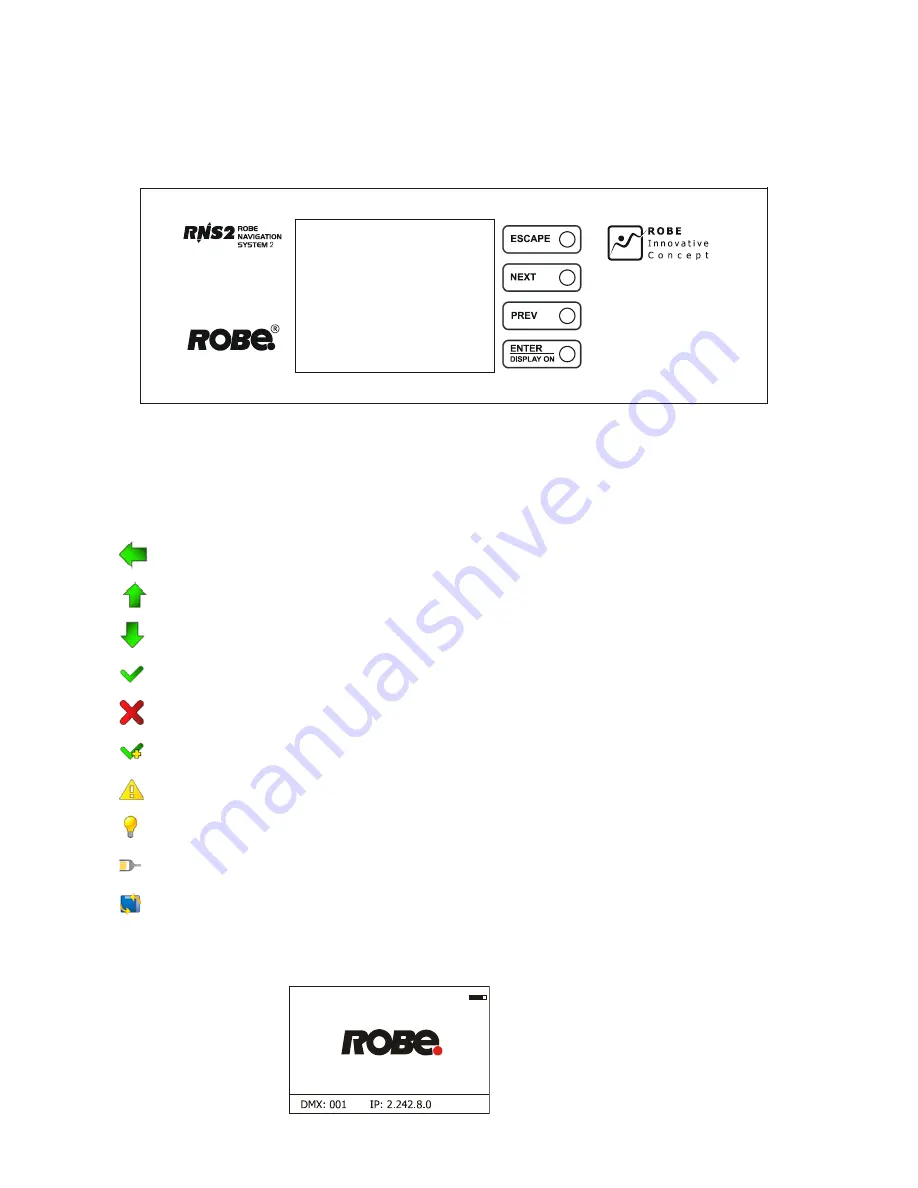
Control buttons on the front panel:

[ESCAPE] button used to leave the menu without saving changes.

[NEXT] , [PREV] buttons for moving between menu items and symbols, adjusting values.

[ENTER/Display On] button used to enter the selected menu (menu item) and to confirm adjusted value.


If the fixture is disconnected from mains, the button switches the touch screen on.

Icons used  in the touch screen menu:

 - 

[back arrow] used to move  back to the previous screen (menu).

 - 

[up arrow] used to move up on the previous page. 

 - 

[down arrow] used to move down on the next page.

 - 

[confirm] used to save adjusted values, to leave menu or to perform desired action.

 - 

[cancel] used to leave menu item without saving changes.

 - 

[copy] used to save adjusted values and copy them to the next prog. step.

 - 

[warning icon] used to indicate some error which has occurred in the fixture.

 - 

[lamp menu] used to switch on/off the lamp and to set lamp functions.

 - 

[Ethernet] used to indicate Ethernet connected.

 - 

[display turn] used to turn the display by 180°. 

The menu page displays icons for each function that you can perform from the touch screen. 

After switching the fixture on, the touch screen shows the screen with the ROBE logo:

The green icon at the top right corner of the 

screen indicates the level of the display battery 

charging. If the whole icon is green, the batery 

is  fully  charged  while  the  red  icon  indicates 

exhausted battery. The batery charges during 

fixture operation.

Summary of Contents for Robin 300 plasma spot

Page 1: ...Version1 6...

Page 2: ...Rigging the fixture 8 4 5 DMX 512 connection 10 4 6 Ethernet connection 11 5 Remotely controllable functions 13 6 Control menu map 14 7 Control menu 17 7 1 Tab Address 18 7 2 Tab Information 18 7 3 T...

Page 3: ...ll connections with the mains with particular caution Make sure that the available voltage is not higher than stated on the rear panel Always plug in the power plug least Make sure that the power swit...

Page 4: ...area below the installation place is blocked when rigging derigging or servicing the fix ture Always fix the fixture with an appropriate safety rope Fix the safety rope at the correct hole only Only...

Page 5: ...SCAPE button 3 NEXT button 4 ENTER DISPLAY ON button 5 PREV button The head should be locked for transportation the tilt lock latch 2 and the pan lock latch 3 have to be in the locked positions To unl...

Page 6: ...t automatically adjusts to any 50 60Hz AC power source from 100 240 Volts Install a suitable plug on the power cord note that the cores in the power cord are coloured according to the following table...

Page 7: ...under the distance stop and push the gobo module into hole in the static gobo wheel 5 Replace the top cover before applying power Rotating gobos 1 Disconnect the fixture from mains and allow it to coo...

Page 8: ...ifications do not attempt the installation yourself but instead use a professional structural rigger Improper installation can result in bodily injury or damage to property The fixture has to be insta...

Page 9: ...Pull the safety wire 2 through the carrying handles 5 and around the truss 6 as shown on the pictures below Securing the fixture via one safety wire Securing the fixture via two safety wires When inst...

Page 10: ...er directly with the DMX input of the first fixture in the DMX chain If you wish to connect DMX controllers with other XLR out puts you need to use adapter cables Building a serial DMX chain Connect t...

Page 11: ...6 RX 3 RX 7 Not connected 4 Not connected 8 Not connected Patch cables that connect fixtures to the hubs or LAN sockets are wired 1 1 that is pins with the same numbers are connected together 1 1 2 2...

Page 12: ...ect the DMX output of this fixture with the input of the next fixture until all fixtures are connected to the DMX chain Caution At the last fixture the DMX chain has to be terminated with a terminator...

Page 13: ...nuous range of colors may be achieved by varying the amount of each filter from 0 to 100 Colour temperature correction filter lowers the colour temperature from 6000 K to 3200 K Note After 1500 operat...

Page 14: ...Lamp On Time Total Hours Resetable Hours Lamp Strikes Total Strikes Resetable Strikes Air Filters Elapsed Time Alert Period 10 300 Fixture Temperatures Head Temperature Current Maximum NonRes Maximum...

Page 15: ...Wheel Moving Off On Gobo Wheels Moving Off On Init Effect Positions Pan 0 255 Dimmer Fine 0 255 Screen Settings Display Intensity 1 10 Screen Saver Delay Off 10min Touchscreen Lock Off 10min Recalibr...

Page 16: ...ay Program 3 Edit Program Edit Program 1 Start Step 1 100 End Step 1 100 Edit Program Steps Step 1 Pan 0 255 Dimmer Fine 0 255 Step Time 0 25 5s Step 100 Pan 0 255 Dimmer Fine 0 255 Step Time 0 25 5s...

Page 17: ...to move back to the previous screen menu up arrow used to move up on the previous page down arrow used to move down on the next page confirm used to save adjusted values to leave menu or to perform d...

Page 18: ...rtnet MaNet Fixture receives Artnet protocol or MANet every fixture has to be connected to the Ethernet network Ethernet To DMX Fixture receives Artnet protocol from the Ethernet input and sends DMX d...

Page 19: ...ture head since the counter was last reset In order to reset this counter to 0 touch the text box next to the item Maximum Res Driver Temperature The menu shows temperature of the plasma source driver...

Page 20: ...rors Frost Errors Dimmer 2 Errors Cyan Errors Colour Errors Magenta Errors Gobo Errors Yellow Errors Gobo Carousel Errors CTO Errors Static Gobo Errors Clean Air Filters Iris Errors Overheated Focus E...

Page 21: ...bles to close light output while the pan tilt coordinates are changing Colour Wheel Moving The menu item enables to close light output while the colour wheel is moving Gobo Wheel Moving The menu item...

Page 22: ...ons on the wall ceiling or ground without any pan tilt move ment Adjust the pan tilt zoom focus and hot spot to desired positions an start test sequences by touching the green icon Music Trigger Use t...

Page 23: ...from small to large Figure of triangle from small to large Figure of star from small to large Figure of cross from small to large DMX 0 1 127 128 129 130 255 Pan Tilt Macro Speed No macro generation...

Page 24: ...n the menu Personality will be set to their default factory values To update software in the fixture I Installation of the DMX Software Uploader 1 DMX Software Uploader program is available from the R...

Page 25: ...ing can be temporarily overwritten by the DMX value at the channel Power Special functions ranges of 30 39 DMX and 40 49 DMX Note because the plasma source comes up from 20 of its nominal power to the...

Page 26: ...uit malfunctions sen sor failed or magnet is missing or the stepping motor is defective or its driving IC on the PCB The yoke is not located in the default position after the reset of the fixture Colo...

Page 27: ...sage informs you that the lamp is too warm General Failure The message informs you that the internal failure was sensed as temp sensor failure 28V Failure The message informs you that the lamp was shu...

Page 28: ...e setting and addressing Gravitation sensor for auto screen positioning Battery backup of the touch screen Readout fixture and lamp usage receiving DMX values temperatures etc Built in analyzer for ea...

Page 29: ...recommended under no circumstances should alcohol or solvents be used DANGER Disconnect from the mains before starting any maintenance work The front objective lens will require weekly cleaning as smo...

Page 30: ...wer if Shutter strobe channel 0 DMX step 50 59 Pan Tilt speed mode step 60 69 Pan Tilt time mode step 70 79 Blackout while pan tilt moving step 80 89 Disabled blackout while pan tilt moving step 90 99...

Page 31: ...random colour selection from fast to slow proportional 8 Colour wheel fine positioning 0 255 Fine positioning proportional 9 8 6 Cyan 0 255 Cyan 0 white 255 full cyan proportional 10 9 7 Magenta 0 25...

Page 32: ...of Rot Gobo Selection from max to min 0 25 5sec proportional 15 14 12 Static gobo wheel Continual Positioning In range 0 64 DMX is possible fine gobo positioning set value on channel 16 0 Open hole pr...

Page 33: ...ex set indexing on channel 18 16 14 0 3 Open hole step 4 7 Gobo 1 step 8 11 Gobo 2 step 12 15 Gobo 3 step 16 19 Gobo 4 step 20 23 Gobo 5 step 24 27 Gobo 6 step 28 31 Gobo 7 step Rotation set rotation...

Page 34: ...bo indexing rotation fine 0 255 Fine indexing rotation proportional 20 17 15 Prism 0 19 Open position hole step 20 127 3 facet rotating prism step 128 255 Prism gobo macros 128 135 Macro 1 step 136 14...

Page 35: ...proportional 29 23 21 Shutter strobe 0 Shutter closed lamp power redused to 20 of nomin power step 1 31 Shutter closed full lamp power step 32 63 Shutter open full lamp power step 64 95 Strobe effect...

Reviews: