37
8.
Connect boiler flue adapter to flue damper for each boiler
in cascade system. Ensure flue adapters allow for 3° or
2 in. per 3 ft. slope of horizontal collectors back towards
condensate collector.
9.
Connect intake air screen to flue adapter for each boiler in
cascade system.
10.
Connect cascade vent system to flue connection on top of
boilers.
11.
Connect end cap and condensate trap to horizontal
common vent pipe.
12.
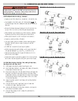
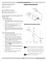
Secure flue adapters using approved clamps to wall.
Ensure clamps are connected minimum of 10 in. from top
of boiler. See Figure 6-32.
13.
Secure approved clamp around flue adapter. Ensure clamp
is locked in to proper position. See Figure 6-32.
A. Position 1 - Clamping around bell end of adapter.
B.
Position 2 - Clamping around flue pipe adapter.
14.
Maximum distance between supports for horizontal pipes
3 ft 4 in. Maximum distance between supports for vertical
pipes 6 ft 7 in. See Figure 6-33.
15.
Fully tighten horizontal common vent pipe supports.
6 - COMBUSTION AIR AND VENT PIPING
FIGURE 6-32 Secure Clamp around Flue Adapter
FIGURE 6-33 Maximum Distance Between Supports
Horizontal
Vertical
P/N 240011654, Rev. C [06/08/2017]


