26
6 - COMBUSTION AIR AND VENT PIPING
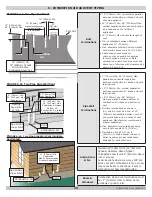
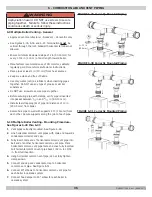
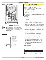
FIGURE 6-8 - Two Pipe Polypropylene System
Adapter
Front View
Left side View
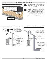
FIGURE 6-9 - Separated Horizontal Flue Termination
Boiler
Note
Ensure minimum downward slope of 2 in (50 mm)
for every 4 ft (1 m) of duct length toward boiler.
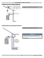
FIGURE 6-10 - Separated Flue Termination (Natalini Venting Only)
6.5 Two Pipe Polypropylene System
Two pipe venting allows for exhaust flue and intake flue to be
separated from each other. Fresh air may be drawn in at a
different area from where the flue terminal is located.
Splitting kit consists of adaptor and of intake air vent adaptor.
See Figure 6-8.
Use screws and seals removed from the cap for the air duct
adaptor.
90° elbow allows boiler to connect to the venting termination
regardless of direction since it can be rotated 360°. It can also
be used to connect the vent with 45° elbow.
Elbow
Total Length Reduction
45°
10" (0.3 m)
90°
2 ft (0.6m)
A.
Separated Horizontal Flue Termination Installation
Options: See Figure 6-9
Maximum length of intake vent (L 1) shall not exceed 49 ft
(15.00 m) -
(L1 + L2) max = 100 ft (30 m)
I
L max = 32' (10 m)
L
L max = 32' ( 10 m)
M
L max = 29' (9 m)
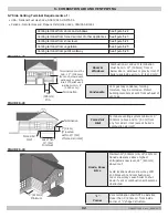
Note
If using indoor air for combustion do not exceed
100ft (30m) exhaust vent pipe.
P/N 240011654, Rev. C [06/08/2017]


